ON-BOARD DIAGNOSTIC (DYNAMIC STABILITY CONTROL)
P81
P
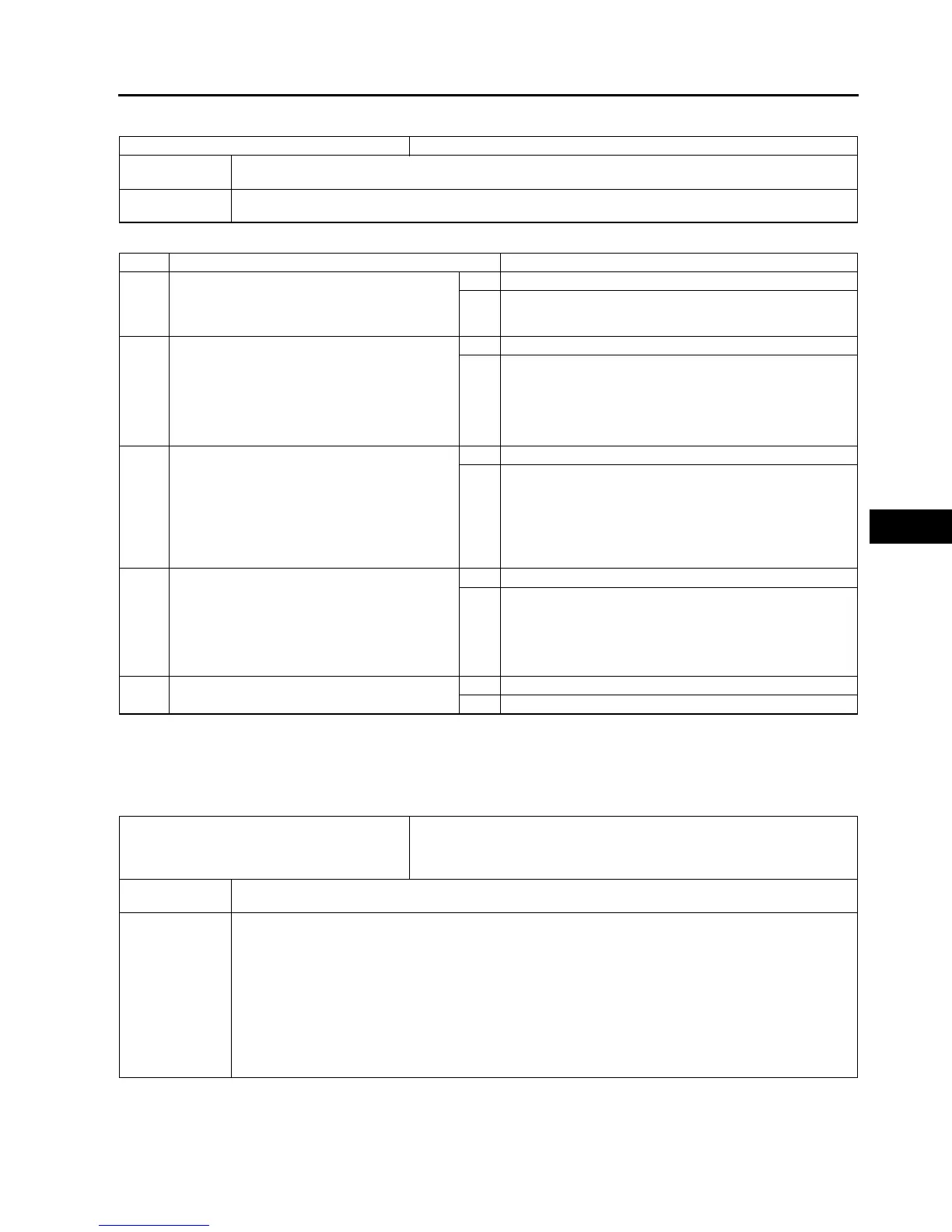
DTC C1140
A6E697367650W11
Diagnostic procedure
End Of Si e
DTC C1145, C1155, C1165, C1175
A6E697367650W12
Caution
•
••
• When attaching the tester lead to the DSC HU/CM connector the SST (49 G066 004) must be used.
DTC C1140 DSC HU/CM (pump)
DETECTION
CONDITION
Right front and left rear wheels, or left front and right rear wheel-lock is detected during DSC operation.
POSSIBLE
CAUSE
Stuck pump motor in DSC HU/CM
STEP INSPECTION ACTION
1 INSPECT DSC HU/CM OPERATION
• Perform DSC HU/CM system inspection.
(See P35 DSC SYSTEM INSPECTION)
• Is it okay?
Yes Go to next step.
No Replace DSC HU/CM, then go to Step 4.
2 INSPECT CONVENTIONAL BRAKE
OPERATION
• Inspect brake fluid level.
• Start engine.
• Perform a road test to verify conventional
vehicle braking performance.
• Is there any concern.
Yes Inspect conventional brake line, then go to Step 4.
No Go to next step.
3 INSPECT REAR BRAKE DRAGGING
• Turn ignition key to OFF.
• Jack-up vehicle and support it with safety
stand.
• Release parking brake.
• Turn rear wheel by hand and inspect for rear
brake drag.
• Is rear brake dragging?
Yes Repair parking brake system, then go to next step.
No Go to next step.
4 VERIFY TROUBLESHOOTING COMPLETED
• Clear DTC from memory.
(See P46 Clearing DTCs Procedures)
• Start engine and drive vehicle at 10 km/h
{6.2 mph} or above at least one minute.
• Gradually slow down vehicle and stop.
• Is same DTC present?
Yes Replace DSC HU/CM, then go to next step.
No Go to next step.
5 VERIFY AFTER REPAIR PROCEDURE
• Is there any other DTC present?
Yes Go to applicable DTC inspection.
No Troubleshooting completed.
DTC
C1145
C1155
C1165
C1175
RF wheel-speed sensor
LF wheel-speed sensor
RR wheel-speed sensor
LR wheel-speed sensor
DETECTION
CONDITION
• Abnormal input is detected.
POSSIBLE
CAUSE
• Open or short to ground circuit in harness between DSC HU/CM terminal and wheel-speed sensor(s)
terminal below
DSC HU/CM terminal MRF wheel-speed sensor terminal A
DSC HU/CM terminal IRF wheel-speed sensor terminal B
DSC HU/CM terminal FLF wheel-speed sensor terminal A
DSC HU/CM terminal JLF wheel-speed sensor terminal B
DSC HU/CM terminal KRR wheel-speed sensor terminal A
DSC HU/CM terminal HRR wheel-speed sensor terminal B
DSC HU/CM terminal QLR wheel-speed sensor terminal A
DSC HU/CM terminal NLR wheel-speed sensor terminal B
• Malfunction of wheel-speed sensor(s)