ON-BOARD DIAGNOSTIC (DYNAMIC STABILITY CONTROL)
P77
P
Diagnostic procedure
End Of Si e
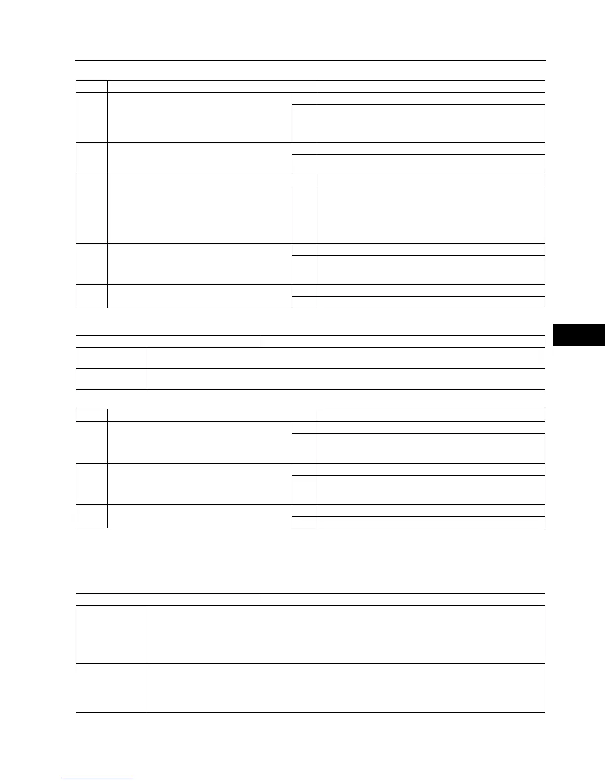
DTC B2477
A6E697367650W07
Diagnostic procedure
End Of Si e
DTC C1095, C1096
A6E697367650W08
Caution
•
••
• When attaching the tester lead to the DSC HU/CM connector the SST (49 G066 004) must be used.
STEP INSPECTION ACTION
1 CHECK TR SWITCH FOR DTCs (ATX)
• Turn ignition key to OFF.
• Connect WDS or equivalent to DLC-2.
• Turn ignition key to ON (engine OFF).
• Is DTC for TR switch obtained?
Yes Follow inspection procedures for TR switch.
No Go to step 4.
2 INSPECT BACK-UP LIGHT SWITCH (MTX)
• Inspect back-up light switch.
• Is it okay?
Yes Go to next step.
No Replace back-up light switch, then go to next step.
3 INSPECT REVERSE SIGNAL CIRCUIT FOR
SHORT TO POWER (MTX)
• Shift select lever to neutral position.
• Turn ignition key to ON.
• Measure voltage between DSC HU/CM
terminal Z and ground.
• Is voltage above 10 V?
Yes Go to next step.
No Replace back-up light switch, then go to next step.
Replace reverse signal circuit, then go to next step.
4 VERIFY TROUBLESHOOTING COMPLETED
• Clear DTC from memory.
(See P46 Clearing DTCs Procedures)
• Is same DTC present?
Yes Replace DSC HU/CM, then go to next step.
No Go to next step.
5 VERIFY AFTER REPAIR PROCEDURE
• Is there any other DTC present?
Yes Go to applicable DTC inspection.
No Troubleshooting completed.
DTC B2477 Module configuration
DETECTION
CONDITION
• Configuration write failure is detected.
POSSIBLE
CAUSE
• Module configuration procedure is not done properly.
STEP INSPECTION ACTION
1 CHECK WHETHER DSC HU/CM IS
CONFIGURED
• Is DSC HU/CM configured?
Yes Go to next step.
No Configurate DSC using WDS or equivalent.
(See P29 ABS (ABS/TCS) or DSC HU/CM
CONFIGURATION)
2 VERIFY TROUBLESHOOTING COMPLETED
• Clear DTC from memory.
(See P46 Clearing DTCs Procedures)
• Is same DTC present?
Yes Replace DSC HU/CM, then go to next step.
No Go to next step.
3 VERIFY AFTER REPAIR PROCEDURE
• Is there any other DTC present?
Yes Go to applicable DTC inspection.
No Troubleshooting completed.
DTC C1095, C1096 Motor relay, pump motor
DETECTION
CONDITION
• C1095 (54):
No motor monitor signal congruency is detected in relation to DSC HU/CM ON signal.
• C1096 (53):
No motor monitor signal congruency is detected in relation to DSC HU/CM OFF signal.
Motor monitor ON signal is not input after specified time when the motor signal is switched from ON
to OFF by DSC HU/CM.
POSSIBLE
CAUSE
• Malfunction of fuse (ABS 60 A)
• Open circuit in harness between DSC HU/CM terminal D and battery positive terminal
• Open circuit in harness between DSC HU/CM terminal B and body ground
• Open or short of motor relay and/or pump motor in DSC HU/CM
• Stuck motor relay and/or pump motor in DSC HU/CM