FRONT SUSPENSION
R13
R
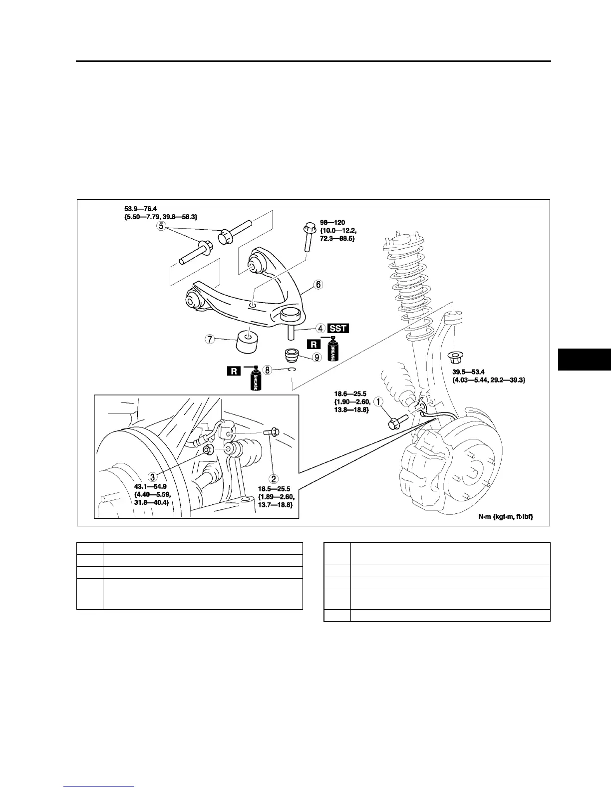
FRONT UPPER ARM REMOVAL/INSTALLATION
A6E741434200W01
Caution
•
••
• Performing the following procedures without first removing the ABS wheel-speed sensor may
possibly cause an open circuit in the harness if it is pulled by mistake. Before performing the
following procedures, remove the ABS wheel-sensor (axle side) and fix it to an appropriate place
where the sensor will not be pulled by mistake while servicing the vehicle.
1. Remove in the order indicated in the table.
2. Install in the reverse order of removal.
3. Inspect the front wheel alignment.
(See R5 FRONT WHEEL ALIGNMENT.)
.
Front Upper Arm Ball Joint Removal Note
1. Support the knuckle using the jack.
A6E7414W035
1 Bolt (ABS wheel-speed sensor)
2 Bolt (brake hose bracket)
3 Nut (stabilizer control link)
4 Front upper arm ball joint
(SeeR13 Front Upper Arm Ball Joint Removal
Note)
5 Bolt (front upper arm)
(See R14 Bolt (Front Upper Arm) Removal Note)
6 Front upper arm
7 Dynamic Damper
8Clip
(See R14 Clip Installation Note)
9 Dust boot