F56
CONTROL SYSTEM
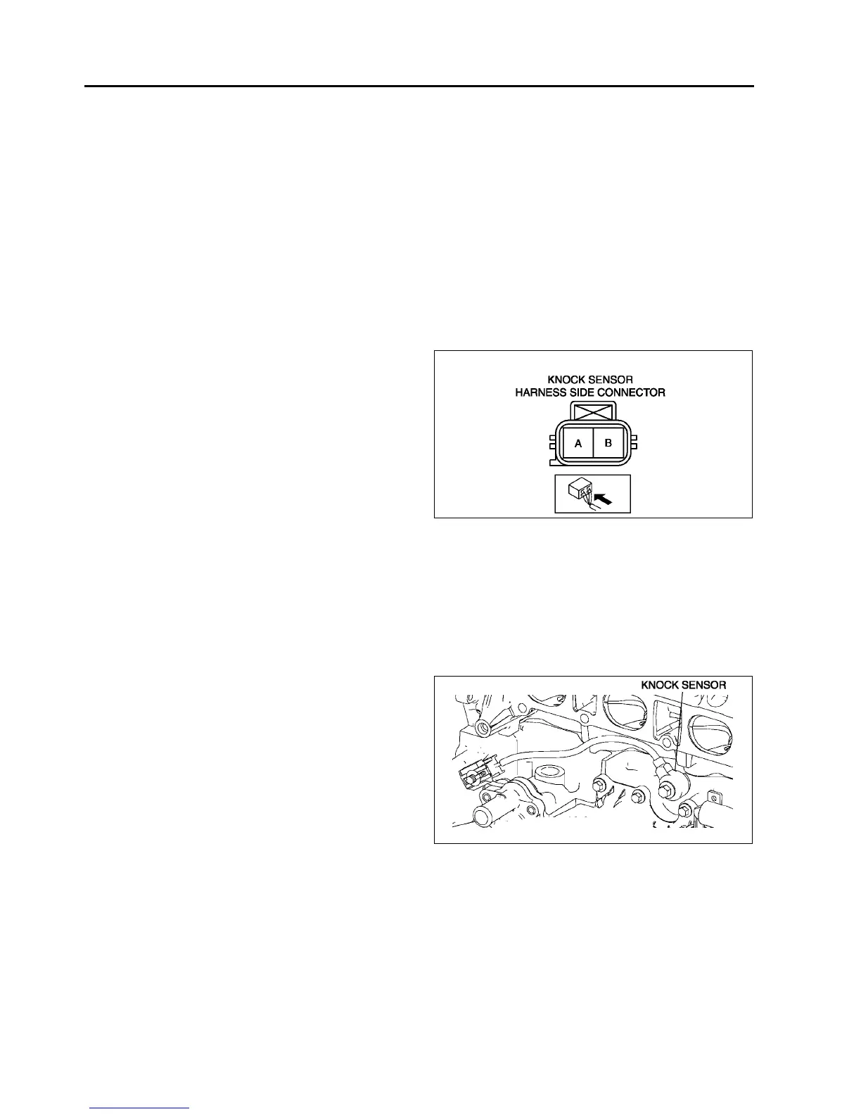
KNOCK SENSOR INSPECTION
A6E394018921W01
Note
• Perform the following test only when directed.
Resistance Inspection
1. Turn the ignition switch to LOCK.
2. Disconnect the knock sensor connector.
3. Measure the resistance between the knock sensor terminals A and B using an ohmmeter.
• If not as specified, replace the knock sensor.
• If the knock sensor is okay, but PID value is out of specification, perform the Circuit Open/Short
Inspection.
Specification
Approx. 4.87 megohms
Circuit Open/Short Inspection
1. Disconnect the PCM connector. (See F43 PCM
REMOVAL/INSTALLATION.)
2. Inspect the following wiring harnesses for open or
short. (Continuity check)
Open circuit
• If there is no continuity, the circuit is open. Repair
or replace the harness.
Knock sensor terminal A (harness-side) and
PCM terminal 2S (harness-side)
Knock sensor terminal B (harness-side) and
PCM terminal 2P (harness-side)
Short circuit
• If there is continuity, the circuit is shorted. Repair
or replace the harness.
Knock sensor terminal A (harness-side) and power supply
Knock sensor terminal A (harness-side) and body GND
Knock sensor terminal B (harness-side) and power supply
Knock sensor terminal B (harness-side) and body GND
End Of Sie
KNOCK SENSOR REMOVAL/INSTALLATION
A6E394018921W02
1. Remove the intake manifold. (See F10 INTAKE-AIR SYSTEM REMOVAL/INSTALLATION.)
2. Remove the knock sensor attachment bolt to
remove the knock sensor.
3. Install in the reverse order of removal.
Tightening torque
16.223.8 N·m
{1.662.42 kgf·m, 12.017.5 ft·lbf}
End Of Sie
HEATED OXYGEN SENSOR (HO2S) INSPECTION
A6E394018861W01
HO2S Voltage Inspection
Note
• Perform the following inspection only when directed.
1. Warm up the engine and run it at idle.
2. Disconnect the HO2S connector.
A6E3940W015
A6E3940W016