CONTROL SYSTEM
F43
F
PCM REMOVAL/INSTALLATION
A6E394018880W01
Note
• For replace the PCM, Setup the WDS and perform the PCM configuration. (See F50 PCM
CONFIGURATION.)
1. Disconnect the negative battery cable.
2. For R.H.D, perform the following procedures.
(1) Remove the front side trim (left-side).
(2) Partially peel back the flower covering.
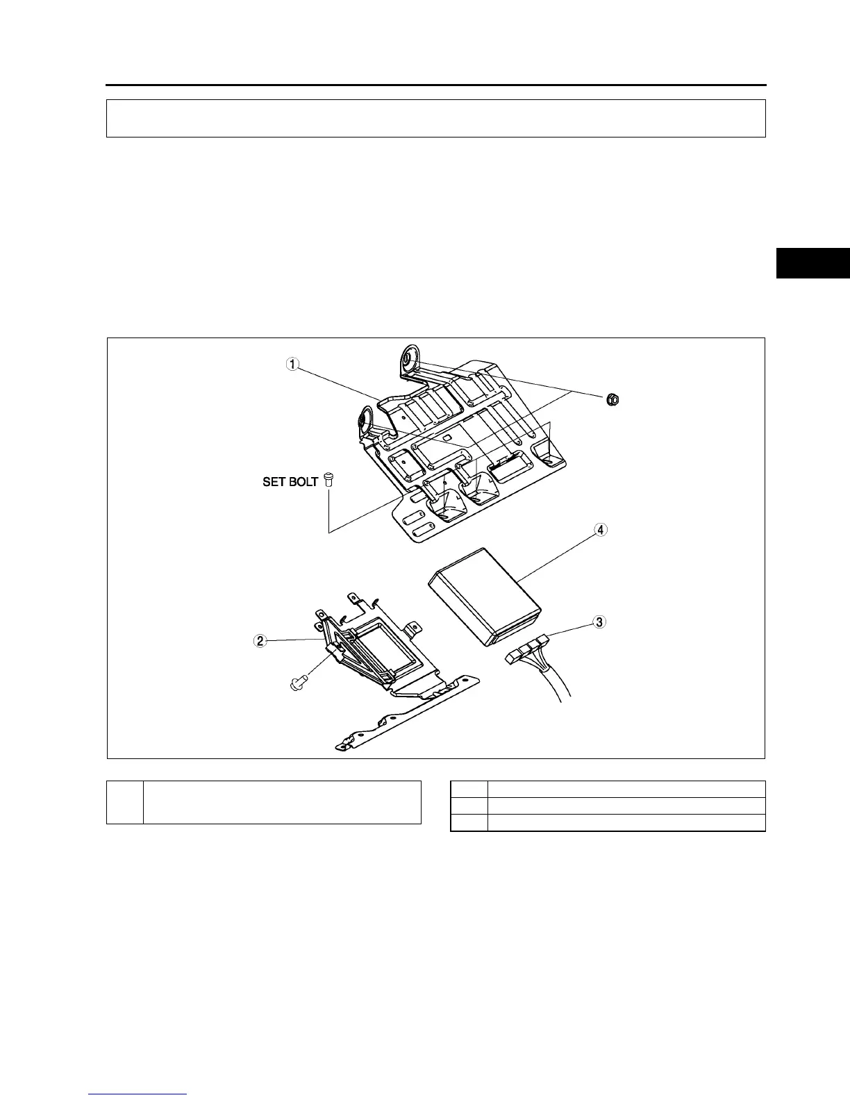
3. Remove in the order indicated in the table.
4. Install in the reverse order of removal.
U.K. specs.
.
CONTROL SYSTEM
A6E3940W002
1 PCM cover No. 1
(See F44 Set Nut/bolt Removal Note)
(See F44 Set Nut/bolt Installation Note)
2 PCM cover No. 2
3 PCM connector
4PCM