ON-BOARD DIAGNOSTIC
F79
F
Diagnostic procedure
End Of Sie
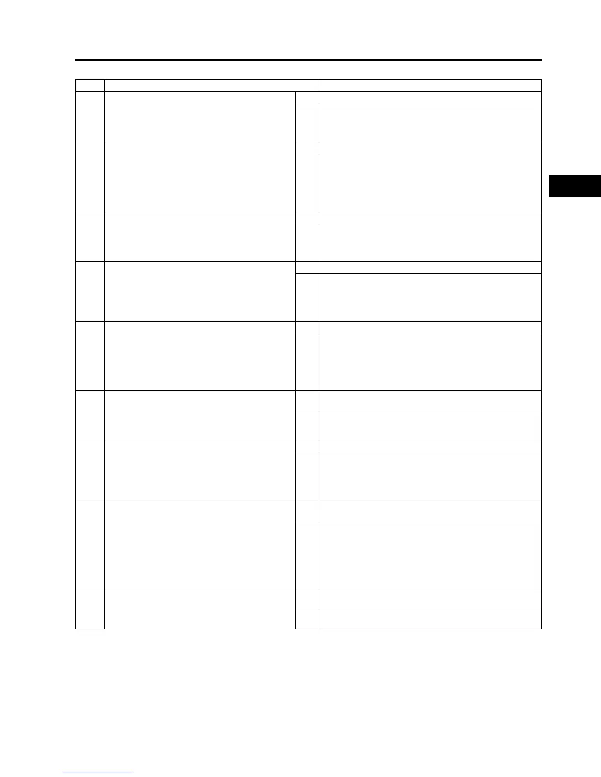
STEP INSPECTION ACTION
1 PERFORM DTC CONFIRMATION PROCEDURE
• Perform DTC CONFIRMATION PROCEDURE.
(See F66 DTC CONFIRMATION
PROCEDURE.)
• Is same DTC present?
Yes Go to next step.
No Intermittent concern exists. Go to INTERMITTENT
CONCERN TROUBLESHOOTING procedure.
(See F227 INTERMITTENT CONCERN
TROUBLESHOOTING.)
2 INSPECT POOR CONNECTION OF REAR HO2S
CONNECTOR
• Turn ignition key to OFF.
• Disconnect rear HO2S connector.
• Inspect for poor connection (damaged, pulled-
out pins, corrosion, etc.).
• Are there any malfunctions?
Yes Repair or replace terminal, then go to Step 8.
No Go to next step.
3 INSPECT REAR HO2S HEATER
• Inspect rear HO2S heater.
(See F56 HEATED OXYGEN SENSOR
(HO2S) INSPECTION.)
• Is rear HO2S heater okay?
Yes Go to next step.
No Replace rear HO2S, then go to Step 8.
4 INSPECT REAR HO2S HEATER POWER
CIRCUIT FOR OPEN CIRCUIT
• Turn ignition key to ON (Engine OFF).
• Measure voltage between rear HO2S terminal
C (harness-side) and body ground.
• Is there voltage B+?
Yes Go to next step.
No Repair or replace harness for open circuit, then go to Step
8.
5 INSPECT POOR CONNECTION OF PCM
CONNECTOR
• Turn ignition key to OFF.
• Disconnect PCM connector.
• Inspect for poor connection (damaged, pulled-
out pins, corrosion, etc.).
• Are there any malfunctions?
Yes Repair terminal, then go to Step 8.
No Go to next step.
6 INSPECT REAR HO2S HEATER CONTROL
CIRCUIT FOR SHORT TO GROUND
• Inspect continuity between rear HO2S terminal
D (harness-side) and body ground.
• Is there any continuity?
Yes Repair or replace harness for short to ground, then go to
Step 8.
No Go to next step.
7 INSPECT HREAR HO2S HEATER CONTROL
CIRCUIT FOR OPEN CIRCUIT
• Remove PCM with PCM connector connected.
• Inspect continuity between rear HO2S terminal
D (harness-side) and PCM terminal 4D.
• Is there any continuity?
Yes Go to next step.
No Repair or replace harness for open circuit, then go to Step
8.
8 VERIFY TROUBLESHOOTING OF DTC P0037
COMPLETED
• Make sure to reconnect all disconnected
connectors.
• Clear DTC from PCM memory using WDS or
equivalent.
• Perform KOEO/KOER self-test.
(See F66 KOEO/KOER SELF-TEST.)
• Is same DTC present?
Yes Replace PCM, then go to next step.
(See F43 PCM REMOVAL/INSTALLATION.)
No Go to next step.
9 VERIFY AFTER REPAIR PROCEDURE
• Perform After Repair Procedure.
(See F66 AFTER REPAIR PROCEDURE.)
• Is there any DTC present?
Yes Go to applicable DTC troubleshooting.
(See F67 DTC TABLE.)
No Troubleshooting completed.