ON-BOARD DIAGNOSTIC
F101
F
Diagnostic procedure
STEP INSPECTION ACTION
1 PERFORM DTC CONFIRMATION PROCEDURE
• Perform DTC CONFIRMATION PROCEDURE.
(See F66 DTC CONFIRMATION
PROCEDURE.)
• Is same DTC present?
Yes Go to next step.
No Intermittent concern exists. Go to INTERMITTENT
CONCERN TROUBLESHOOTING procedure.
(See F227 INTERMITTENT CONCERN
TROUBLESHOOTING.)
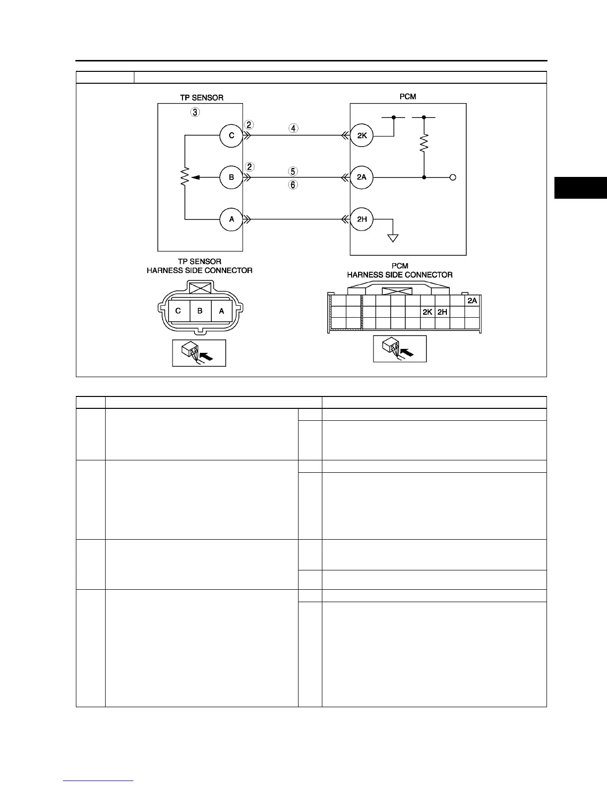
2 CLASSIFY TP SENSOR OR HARNESS
MALFUNCTION
• Connect WDS or equivalent.
• Access TP PID.
• Disconnect TP sensor connector.
• Connect a jumper wire between TP sensor
terminals B and C (harness-side).
• Is voltage above 4.9 V?
Yes Go to next step.
No Go to step 4.
3 INSPECT TP SENSOR
• Perform TP sensor inspection.
(See F51 THROTTLE POSITION (TP)
SENSOR INSPECTION.)
• Is TP sensor okay?
Yes Inspect for poor TP sensor connector terminal C
connection. Repair or replace as necessary, then go to
Step 7.
No Replace TP sensor, then go to Step 7.
4 INSPECT POWER SUPPLY CIRCUIT VOLTAGE
AT TP SENSOR CONNECTOR
Note
• If DTC P0107 and P2228 are also retrieved
with P0122, go to CONSTANT VOLTAGE
troubleshooting procedure.
• Turn ignition key to ON (Engine OFF).
• Inspect voltage at TP sensor terminal 2k
(harness-side).
• Is there voltage within 4.55.5 V?
Yes Go to next step.
No Repair or replace open circuit between TP sensor
connector terminal C and PCM connector terminal 2K
(harness-side).
Then, then go to Step 7.
DTC P0122 TP circuit low input