ON-BOARD DIAGNOSTIC
F103
F
Diagnostic procedure
STEP INSPECTION ACTION
1 PERFORM DTC CONFIRMATION PROCEDURE
• Perform DTC CONFIRMATION PROCEDURE.
(See F66 DTC CONFIRMATION
PROCEDURE.)
• Is same DTC present?
Yes Go to next step.
No Intermittent concern exists. Go to INTERMITTENT
CONCERN TROUBLESHOOTING procedure.
(See F227 INTERMITTENT CONCERN
TROUBLESHOOTING.)
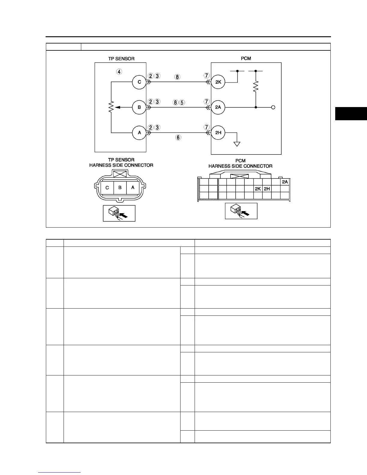
2 INSPECT TP SENSOR CONNECTOR
• Turn ignition key to OFF.
• Verify that the TP sensor connector is
connected securely.
• Is connector okay?
Yes Go to next step.
No Connect the connector securely, then go to Step 9.
3 INSPECT POOR CONNECTION OF TP SENSOR
CONNECTOR
• Disconnect TP sensor connector.
• Inspect for poor connection (damaged, pulled-
out terminals, corrosion, etc.).
• Is there any malfunction?
Yes Repair or replace suspected terminal, then go to Step 9.
No Go to next step.
4 INSPECT TP SENSOR
• Perform TP sensor inspection.
(See F51 THROTTLE POSITION (TP)
SENSOR INSPECTION)
• Is TP sensor okay?
Yes Go to next step.
No Replace TP sensor, then go to Step 9.
5 INSPECT TP SENSOR SIGNAL CIRCUIT FOR
SHORT TO POWER
• Turn ignition key to ON (Engine OFF).
• Measure voltage between terminal B and body
ground.
• Is voltage above 4.9?
Yes Repair or replace short to power circuit. Then, go to Step 9.
No Go to next step.
6 VERIFY TP SENSOR GROUND CIRCUIT FOR
OPEN CIRCUIT
• Inspect continuity between TP sensor
connector terminal A and body ground.
• Is there continuity?
Yes Repair or replace open circuit between TP sensor
connector terminal A (harness-side) and PCM connector
terminal 2H (harness-side). Then, go to Step 9.
No Go to next step.
DTC P0123 TP circuit high input