ON-BOARD DIAGNOSTIC
F127
F
Diagnostic procedure
STEP INSPECTION ACTION
1 PERFORM DTC CONFIRMATION PROCEDURE
• Perform DTC CONFIRMATION PROCEDURE.
(See F66 DTC CONFIRMATION
PROCEDURE.)
• Is same DTC present?
Yes Go to next step.
No Intermittent concern exists. Go to INTERMITTENT
CONCERN TROUBLESHOOTING procedure.
(See F227 INTERMITTENT CONCERN
TROUBLESHOOTING.)
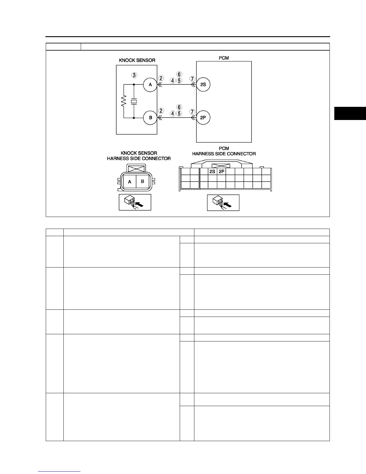
2 INSPECT KNOCK SENSOR CONNECTOR
TERMINAL
• Turn ignition key to OFF.
• Disconnect knock sensor connector.
• Check for poor connection at terminals A and B
(damaged, pulled-out pins, corrosion, etc.).
• Is there any malfunction?
Yes Repair terminal, then go to Step 8.
No Go to next step.
3 INSPECT KNOCK SENSOR
• Perform knock sensor inspection.
(See F56 KNOCK SENSOR INSPECTION)
• Is knock sensor okay?
Yes Go to next step.
No Replace knock sensor, then go to next step.
4 INSPECT KNOCK SENSOR CIRCUITS FOR
OPEN CIRCUIT
• Disconnect knock sensor connector.
• Inspect continuity between the following
circuits:
Knock sensor female terminal A (harness-
side) and PCM terminal 2S (harness-side)
Knock sensor female terminal B (harness-
side) and PCM terminal 2P (harness-side)
• Are there continuities?
Yes Go to next step.
No Repair or replace suspected wiring harness, then go to
Step 8.
5 INSPECT KNOCK SENSOR CIRCUITS FOR
SHORT TO GROUND
• Inspect continuity between following circuits:
Knock sensor female terminal A (harness-
side) and body ground
Knock sensor female terminal B (harness-
side) and body ground
• Are there continuities?
Yes Repair or replace suspected wiring harness, then go to
Step 8.
No Go to next step.
DTC P0327 Knock sensor circuit low input