ON-BOARD DIAGNOSTIC
F131
F
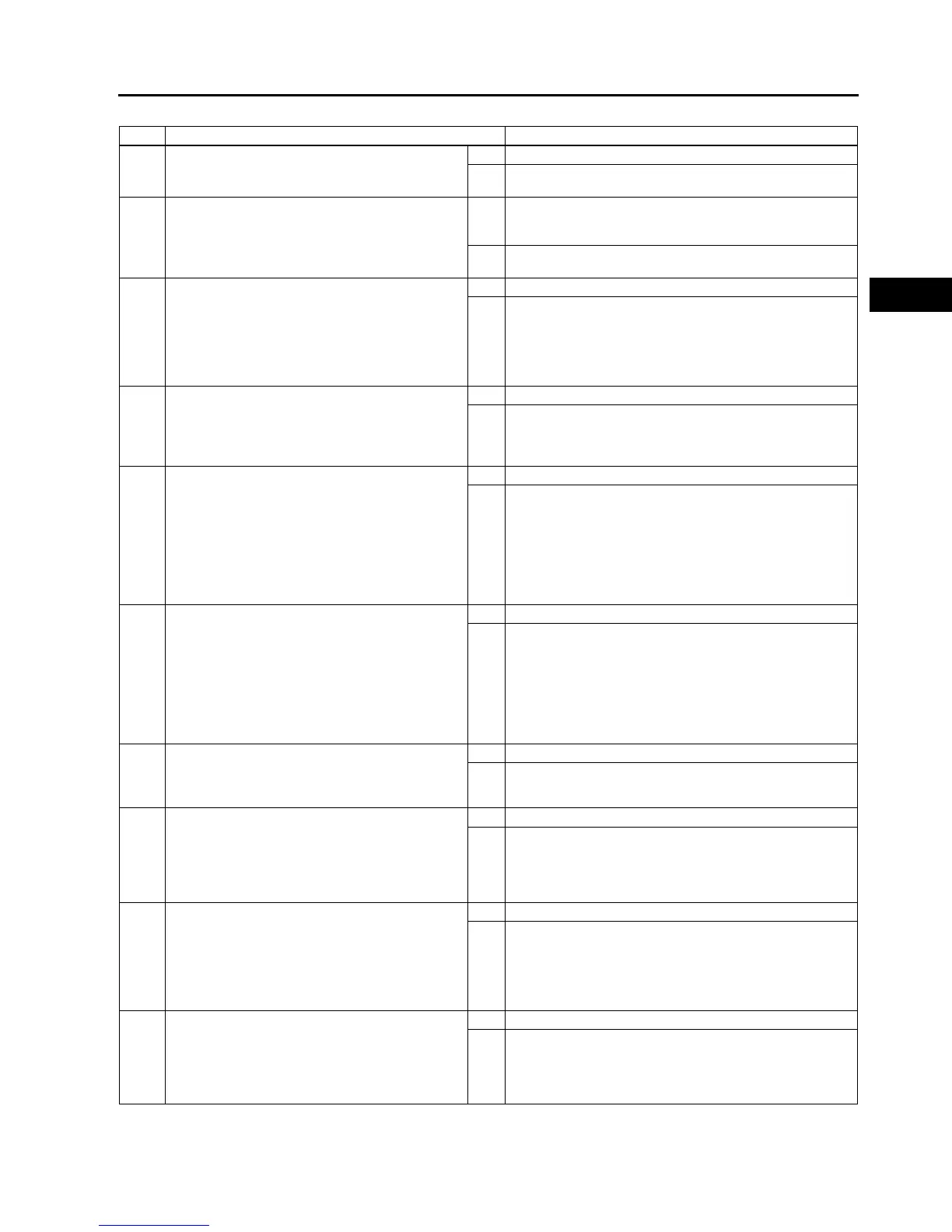
Diagnostic procedure
STEP INSPECTION ACTION
1 VERIFY FREEZE FRAME DATA HAS BEEN
RECORDED
• Has FREEZE FRAME DATA been recorded?
Yes Go to next step.
No Record FREEZE FRAME DATA on repair order, then go to
next step.
2 VERIFY RELATED SERVICE INFORMATION
AVAILABILITY
• Check for related Service Information
availability.
• Is any related Service Information available?
Yes Perform repair or diagnosis according to available Service
Information.
• If vehicle is not repaired, go to next step.
No Go to next step.
3 VERIFY CKP SENSOR VOLTAGE
• Disconnect CKP sensor connector.
• Connect voltmeter between CKP sensor
connector terminals A and B (sensor-side).
• Inspect the voltage in AC range while cranking
the engine.
• Is any voltage reading?
Yes Go to next step.
No Go to step 10.
4 INSPECT POOR CONNECTION OF CKP
SENSOR CONNECTOR
• Verify that the CKP sensor connector is
connected securely.
• Is connector okay?
Yes Go to next step.
No Reconnect the connector, then go to Step 11.
5 INSPECT CKP CIRCUIT FOR SHORT TO
POWER
• Turn ignition key OFF
• Disconnect CKP sensor connector.
• Turn ignition key ON (Engine OFF).
• Measure voltage between following terminals
CKP sensor terminal A
CKP sensor terminal B
• Is any voltage reading?
Yes Repair or replace suspected harness, then go to Step 11.
No Go to next step.
6 INSPECT CKP CIRCUIT FOR SHORT TO
GROUND
• Inspect continuity between following terminal
and body ground:
CKP sensor connector terminal A (harness-
side)
CKP sensor connector terminal B (harness-
side)
• Is there any continuity?
Yes Repair or replace suspected harness, then go to Step 11.
No Go to next step.
7 INSPECT CKP CIRCUITS FOR SHORTS
• Inspect continuity between CKP sensor
connector terminals A and B (harness-side).
• Is there any continuity?
Yes Repair or replace suspected harness, then go to Step 11.
No Go to next step.
8 INSPECT POOR CONNECTION OF PCM
CONNECTOR
• Disconnect PCM connector.
• Inspect for poor connection (damaged, pulled-
out terminals, corrosion, etc.).
• Is there any malfunction?
Yes Repair terminal, then go to Step 11.
No Go to next step.
9 INSPECT CKP CIRCUIT FOR OPEN
• Inspect continuity between following circuits:
CKP sensor terminal A (harness-side) and
PCM terminal 2D (harness-side)
CKP sensor terminal B (harness-side) and
PCM terminal 2G (harness-side)
• Is there continuity?
Yes Go to Step 11.
No Repair or replace suspected harness, then go to Step 11.
10 INSPECT CKP SENSOR
• Turn ignition key to OFF.
• Perform CKP sensor inspection.
(See F54 CRANKSHAFT POSITION (CKP)
SENSOR INSPECTION)
• Is CKP sensor okay?
Yes Go to next step.
No Inspect CKP sensor pulse wheel for damage. Replace CKP
sensor pulse wheel and go to next step.