ON-BOARD DIAGNOSTIC
F165
F
Diagnostic procedure
STEP INSPECTION ACTION
1 PERFORM DTC CONFIRMATION PROCEDURE
• Perform DTC CONFIRMATION PROCEDURE.
(See F66 DTC CONFIRMATION
PROCEDURE.)
• Is same DTC present?
Yes Go to next step.
No Intermittent concern exists. Go to INTERMITTENT
CONCERN TROUBLESHOOTING procedure.
(See F227 INTERMITTENT CONCERN
TROUBLESHOOTING.)
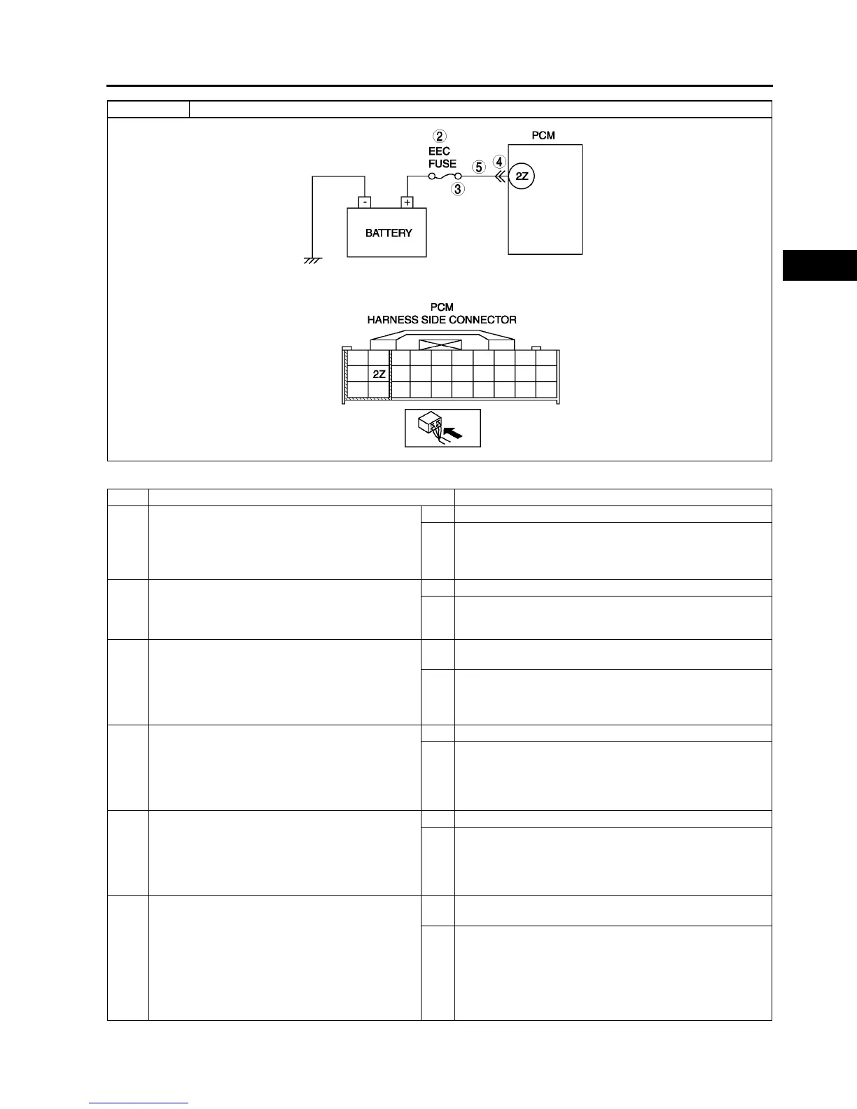
2 INSPECT EEC FUSE
• Turn ignition key to OFF.
• Inspect EEC fuse for failure and proper.
• Is it okay?
Yes Go to step 5.
No • If EEC fuse has been melt down, then go to next step.
• If EEC fuse is not installed correctly, install it correctly
then go to Step 6.
3 INSPECT MONITOR CIRCUIT FOR SHORT TO
GROUND
• Disconnect battery cables.
• Inspect continuity between EEC fuse terminal
and body ground.
• Is there continuity?
Yes Repair or replace harness for short to ground and install
new fuse, then go to Step 6.
No Go to step 6.
4 INSPECT POOR CONNECTION OF PCM
CONNECTOR
• Disconnect PCM connector.
• Inspect for poor connection (damaged, pulled-
out terminals, corrosion, etc.).
• Are there any malfunctions?
Yes Repair terminals, then go to Step 6.
No Go to next step.
5 INSPECT MONITOR CIRCUIT FOR OPEN
CIRCUIT
• Disconnect battery cables.
• Inspect continuity between EEC fuse terminal
and PCM terminal 2Z (harness side).
• Is there any continuity?
Yes Go to next step.
No Repair or replace harness for open, then go to next step.
6 VERIFY TROUBLESHOOTING OF DTC P1562
COMPLETED
• Make sure to reconnect all disconnected
connectors.
• Clear DTC from PCM memory using WDS or
equivalent.
• Perform KOEO/KOER self-test.
(See F66 KOEO/KOER SELF-TEST.)
• Is same DTC present?
Yes Replace PCM, then go to next step.
(See F43 PCM REMOVAL/INSTALLATION.)
No Go to next step.
DTC P1562 PCM +BB (back-up battery) voltage low