AUTOMATIC TRANSAXLE
K31
K
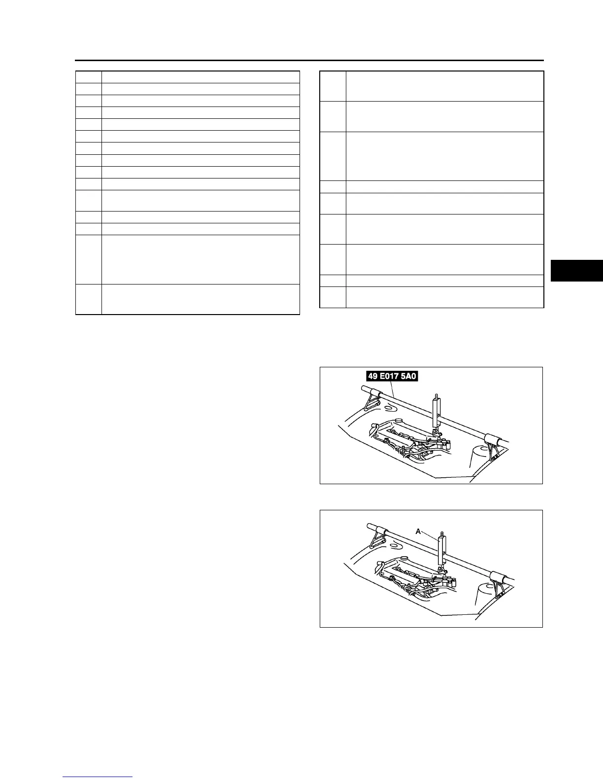
No.1 Engine Mount Bracket Removal Note
1. Support the engine using the SST before removing the No.1 engine mount.
2. Remove the No.1 engine mount.
Transaxle Removal Note
1. Loosen the part marked A and lean the engine
toward the transaxle.
2. Support the transaxle on a jack.
3. Remove the transaxle mounting bolts.
5 TR switch connector
6 Transaxle connector
7 VSS connector
8 Oil dipstick and filler tube
9 Harness bracket
10 Oil hose
11 Selector cable
12 Transaxle mounting bolt (upper side)
13 Starter
14 Endplate cover
15 Tie-rod end ball joint
(See N11 Tie-rod End Ball Joint Removal Note)
16 Stabilizer control link
17 Damper fork
18 Lower arm (front, rear) ball joint
(See R19 Front Lower Arm (Rear) Ball Joint
Removal Note)
(See R16 Front Lower Arm (Front) Ball Joint
Removal Note)
19 Drive shaft
(See M17 DRIVE SHAFT REMOVAL/
INSTALLATION)
20 Drive shaft
(See M17 DRIVE SHAFT REMOVAL/
INSTALLATION)
21 Joint shaft
(See M12 JOINT SHAFT REMOVAL/
INSTALLATION)
22 No.1 engine mount
(See K31 No.1 Engine Mount Bracket Removal
Note)
(See K33 No.1 Engine Mount and No.4 Engine
Mount Bracket Installation Note)
23 Crossmember bracket
24 Crossmember (See R23 FRONT
CROSSMEMBER REMOVAL/INSTALLATION.)
25 Torque converter installation nuts (See K32 Torque
Converter Nuts Removal Note)(SeeK33 Torque
Converter Nuts Installation Note)
26
No.4 engine mount
(See K33 No.1 Engine Mount and No.4 Engine
Mount Bracket Installation Note)
27 Transaxle mounting bolt (lower side)
28 Transaxle (See K31 Transaxle Removal Note)(K
32 Transaxle Installation Note)
A6E5614W049
A6E5614W050