K56
ON-BOARD DIAGNOSTIC
Diagnostic procedure
STEP INSPECTION ACTION
1 VERIFY FREEZE FRAME DATA HAS BEEN
RECORDED
• Has FREEZE FRAME PID DATA been
recorded?
Yes Go to next step.
No Record FREEZE FRAME PID DATA on repair order, then
go to next step.
2 VERIFY RELATED SERVICE INFORMATION
AVAILABILITY
• Check for related Service Bulletins availability.
• Is any related repair Information available?
Yes Perform repair or diagnosis according to available repair
Information.
• If vehicle is not repaired, go to next step.
No Go to next step.
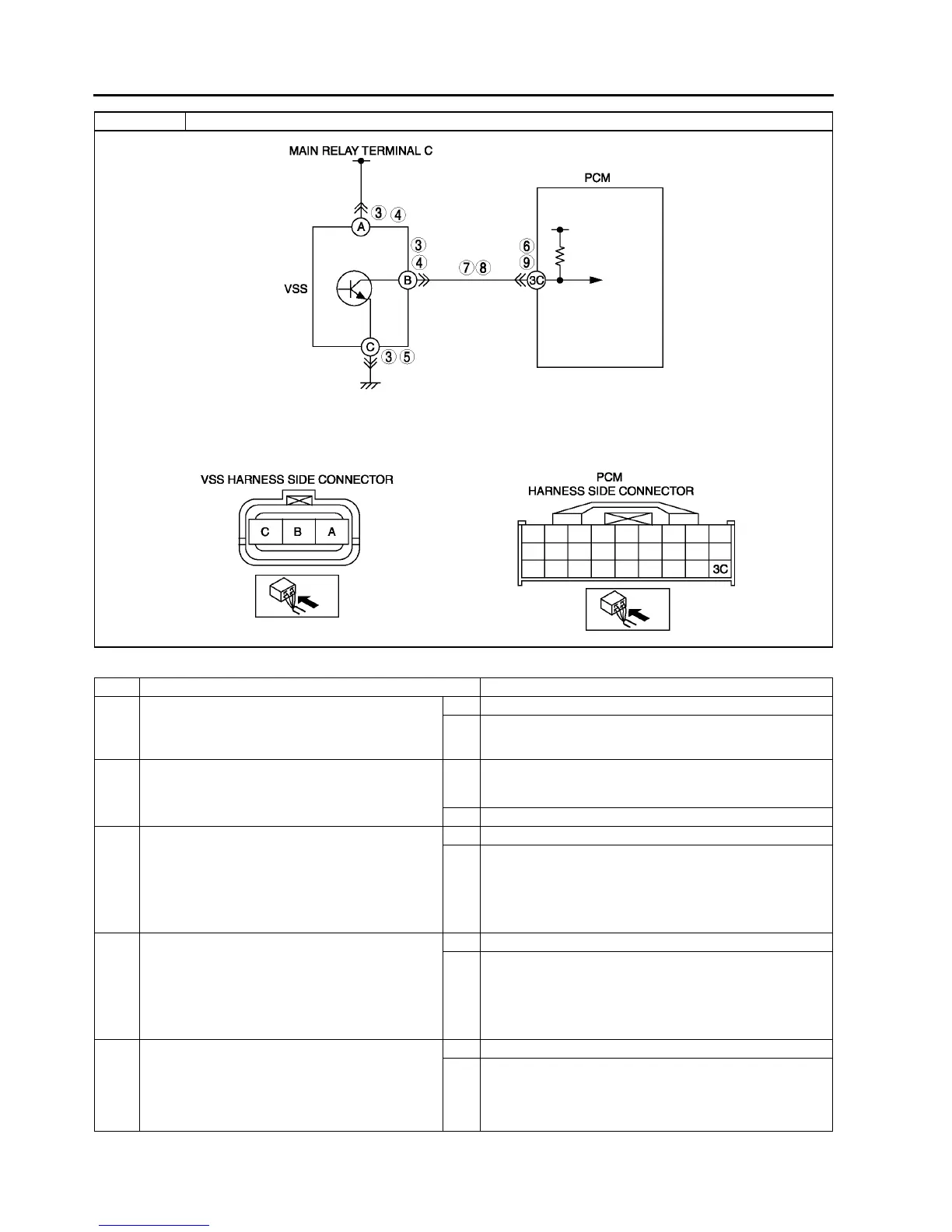
3 INSPECT VSS CONNECTOR FOR POOR
CONNECTION
• Turn ignition key to OFF.
• Disconnect VSS connector.
• Check for poor connection (damaged/pulled-
out terminals, corrosion, etc.).
• Is connection okay?
Yes Go to next step.
No Repair or replace pin or connector, then go to Step 10.
4 INSPECT VSS POWER CIRCUIT FOR OPEN
CIRCUIT
• Verify that VSS connector is disconnected.
• Turn ignition key to ON (Engine OFF).
• Check voltage between VSS terminal A
(harness-side) and ground
• Is voltage reading B+?
Yes Go to next step.
No Repair or replace harness, then go to Step 10.
5 INSPECT VSS GROUND CIRCUIT FOR OPEN
• Turn ignition key to OFF.
• Verify that VSS connector is disconnected.
• Check for continuity between VSS terminal C
(harness-side) and ground
• Is there continuity?
Yes Go to next step.
No Repair or replace harness, then go to Step 10.
DTC P0500 Vehicle speed sensor (VSS) circuit malfunction