K66
ON-BOARD DIAGNOSTIC
Diagnostic procedure
POSSIBLE
CAUSE
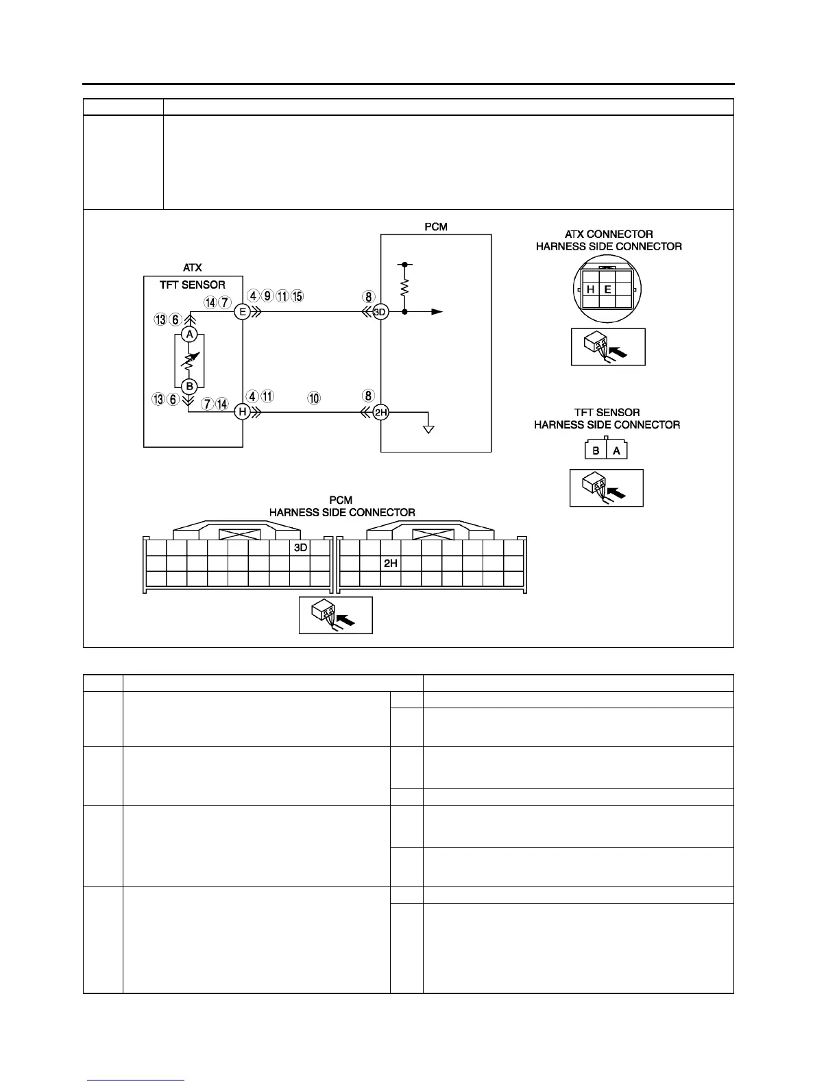
• TFT sensor malfunction
• Open circuit between TFT sensor terminal A and ATX connector terminal E
• Open circuit between TFT sensor terminal B and ATX connector terminal H
• Open circuit between ATX connector terminal E and PCM terminal 3D
• Open circuit between ATX connector terminal H and PCM terminal 2H
• Damaged connectors between TFT sensor and PCM
• PCM malfunction
STEP INSPECTION ACTION
1 VERIFY FREEZE FRAME DATA HAS BEEN
RECORDED
• Has FREEZE FRAME PID DATA been
recorded?
Yes Go to next step.
No Record FREEZE FRAME PID DATA on repair order, then
go to next step.
2 VERIFY RELATED REPAIR INFORMATION
AVAILABILITY
• Check for related Service Bulletins availability.
• Is any related repair information available?
Yes Perform repair or diagnosis according to available repair
information.
• If vehicle is not repaired, go to next step.
No Go to next step.
3 VERIFY CURRENT INPUT SIGNAL STATUS
• Turn ignition key to OFF.
• Connect breakout box to PCM.
• Turn ignition key to ON (engine OFF).
• Measure the voltage at PCM terminal 3D.
• Are voltage readings below 4.67 V?
Yes Go to intermittent concern troubleshooting procedure.
(See F227 INTERMITTENT CONCERN
TROUBLESHOOTING.)
No Go to next step.
4 INSPECT ATX CONNECTOR FOR POOR
CONNECTION
• Turn ignition key to OFF.
• Inspect ATX connector connection.
• Disconnect ATX connector.
• Check for poor connection (damaged/pulled-
out terminals, corrosion etc.).
• Is connection okay?
Yes Go to next step.
No Repair or replace connector and/or terminal, then go to
Step 11.
DTC P0713 Transaxle fluid temperature (TFT) sensor circuit malfunction (open circuit)