DRIVE SHAFT
M25
M
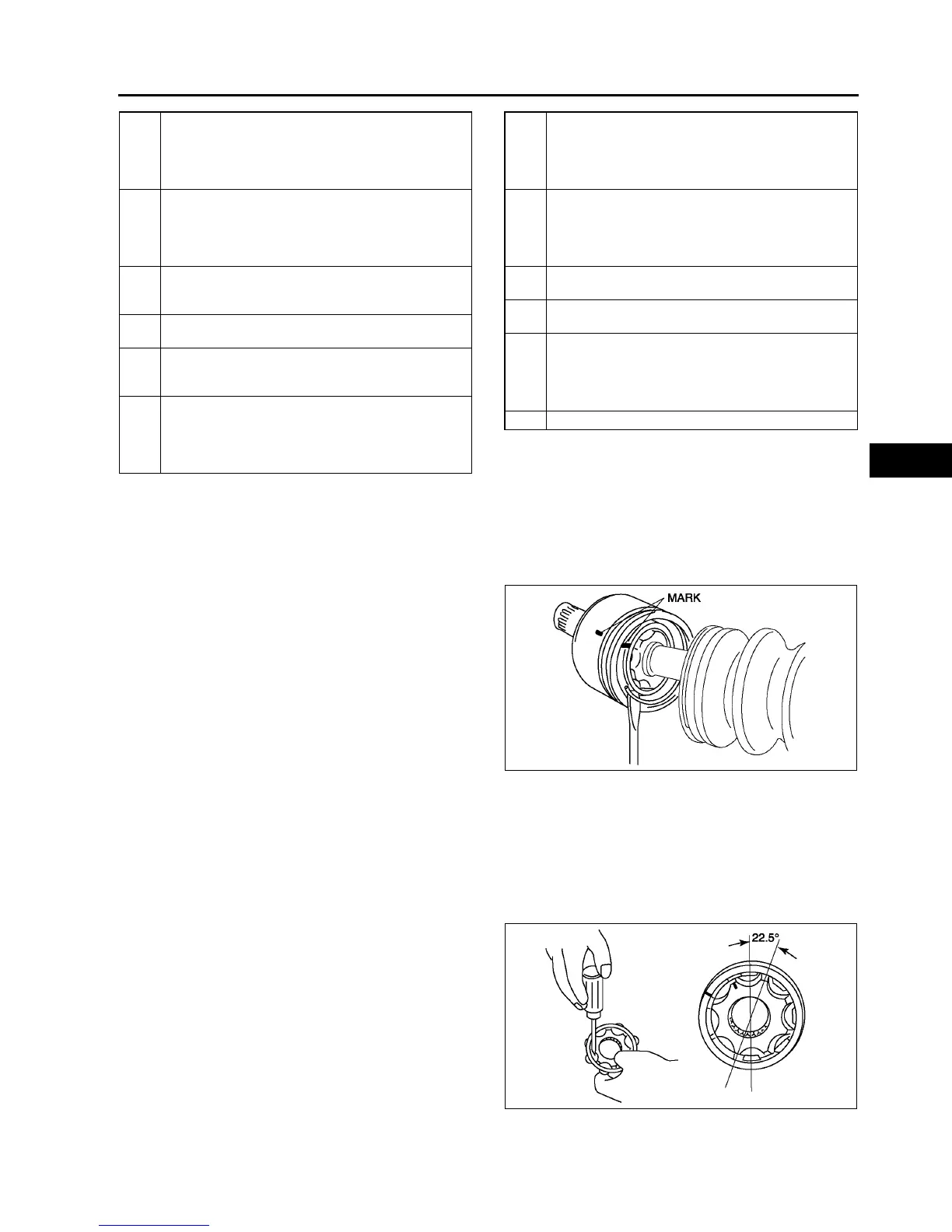
Clip Disassembly Note
1. Mark the drive shaft and outer ring for proper
assembly.
Caution
•
••
• Mark with paint; do not use a punch.
2. Remove the clip.
Balls, Inner Ring, Cage Disassembly Note
1. Mark the inner ring and cage.
Caution
•
••
• Mark with paint; do not use a punch.
2. Remove the snap ring using snap-ring pliers.
3. Turn the cage approximately 30 degree and pull
the cage and balls away from the inner ring.
1 Boot band (wheel side)
(See M20 Boot Band (Wheel Side) Disassembly
Note)
(See M23 Boot Band (Wheel Side) Assembly
Note)
2 Boot band (transaxle side)
See M20 Boot Band (Transaxle Side) Disassembly
Note
See M23 Boot Band (Transaxle Side) Assembly
Note
3Clip
See M25 Clip Disassembly Note
See M26 Outer Ring, Clip Assembly Note
4Outer ring
(See M26 Outer Ring, Clip Assembly Note)
5 Snap ring
(See M26 Cage, Inner Ring, Balls, Snap Ring
Assembly Note)
6Balls
(See M25 Balls, Inner Ring, Cage Disassembly
Note)
(See M26 Cage, Inner Ring, Balls, Snap Ring
Assembly Note)
7 Inner Ring
(See M25 Balls, Inner Ring, Cage Disassembly
Note)
(See M26 Cage, Inner Ring, Balls, Snap Ring
Assembly Note)
8Cage
(See M25 Balls, Inner Ring, Cage Disassembly
Note)
(See M26 Cage, Inner Ring, Balls, Snap Ring
Assembly Note)
9Boot
(See M26 Boot Assembly Note)
10 Dynamic damper
(See M26 Dynamic Damper Assembly Note)
11 ABS sensor rotor
(See M21 ABS Sensor Rotor (With ABS)
Disassembly Note)
(See M22 ABS Sensor Rotor (With ABS) Assembly
Note)
12 Shaft and ball joint component
A6E6316W010
A6E6316W015