CONVENTIONAL BRAKE SYSTEM
P9
P
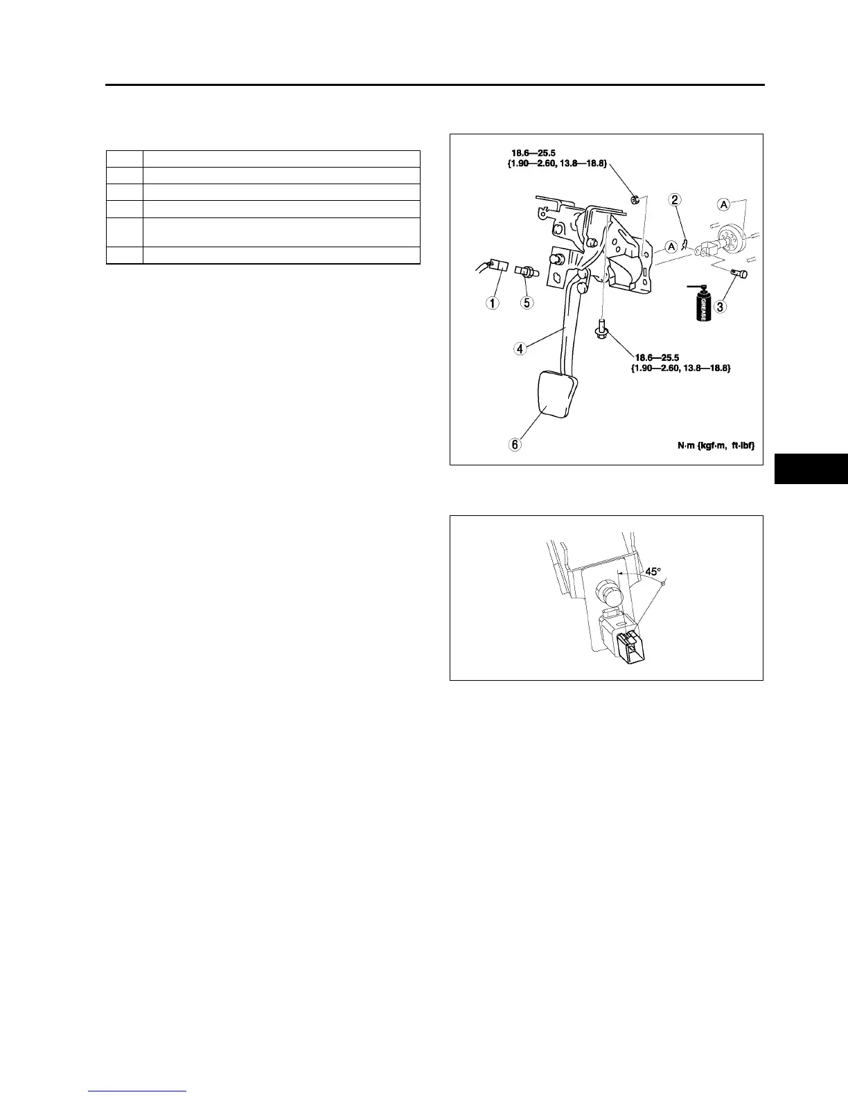
BRAKE PEDAL REMOVAL/INSTALLATION
A6E691243300W02
1. For ATX model, remove the lock unit with brake switch (R.H.D. only).
2. Remove in the order indicated in the table.
3. Install in the reverse order of removal.
Brake switch Installation Note
1. Fix the brake switch on a bracket with pressing down at 50 N {5.1 kgf·m, 37 ft·lbf}.
2. Rotate the brake switch 45°
°°
° counterclockwise.
3. Verify that the brake switch is locked securely.
Note
• Stopper bolt and pedal stopper clearance
adjustment dose not need after the brake
switch is locked securely.
End Of Si e
1 Brake switch connector
2 Spring pin
3Clevis pin
4 Brake pedal
5 Brake switch
(See P9 Brake switch Installation Note)
6 Pedal pad
A6E6912W020
A6E6912W051