ABS/TCS
P29
P
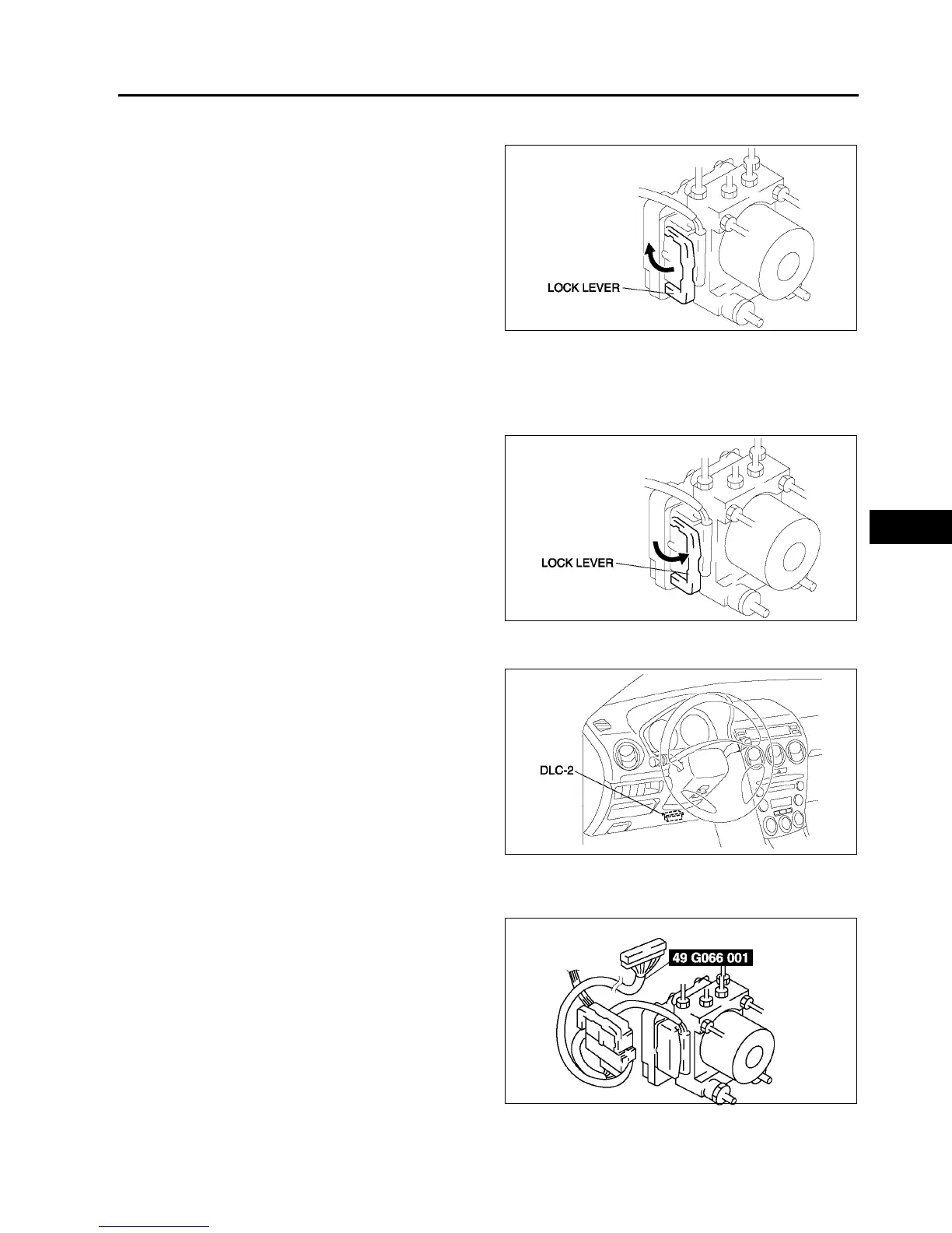
Connector Removal Note
1. Pull the lock lever up and make it unlock.
2. Remove the connector.
ABS HU/CM Removal/Installation Note
1. When removing/installing the ABS HU/CM from/to the vehicle, attach a strip of protective tape on the ABS HU/
CM connector to prevent brake fluid from entering.
Connector Installation Note
1. Verify that the lock lever of the harness connector
is completely pulled up.
End Of Si e
ABS (ABS/TCS) OR DSC HU/CM CONFIGURATION
A6E692143700W02
1. Connect the WDS or equivalent to the DLC-2.
2. Input vehicle information following the direction
on the WDS or equivalent screen.
3. Select Module programming.
4. Select Programmable module installation.
5. Select ABS/TCS.
6. Retrieve DTCs by the WDS or equivalent, then
verify that there is no DTC present.
• If DTC is present, perform applicable DTC
inspection.
End Of Si e
ABS (ABS/TCS) HU/CM INSPECTION
A6E692167650W01
1. Disconnect the negative battery cable.
2. Connect the SST between the ABS (ABS/TCS)
HU/CM and harness connector with the ignition
switch off.
3. Attach the tester leads to the SST and inspect
voltage referring the table below.
A6E6916W006
A6E6916W007
A6E3970W002
A6E6921W005