ABS/TCS
P31
P
*
1
:With TCS
*
2
: Use this terminal at factory only, not used for inspection and repair at field
Inspection Using An Oscilloscope (Reference)
Wheel speed
•
• ABS/TCS HU/CM terminal:
RR : A ( + ) B ( - )
LR : C ( + ) F ( - )
RF : D ( + ) G ( - )
LF : E ( + ) I ( - )
• Oscilloscope setting:
1 V/DIV (Y), 2 ms/DIV (X), AC range
• Vehicle condition: Driving 30 km/h (18.6 mph)
Note
• As vehicle speed increases, period of wave
shortens.
• If there is malfunctioning in the sensor rotor,
wave profile warps.
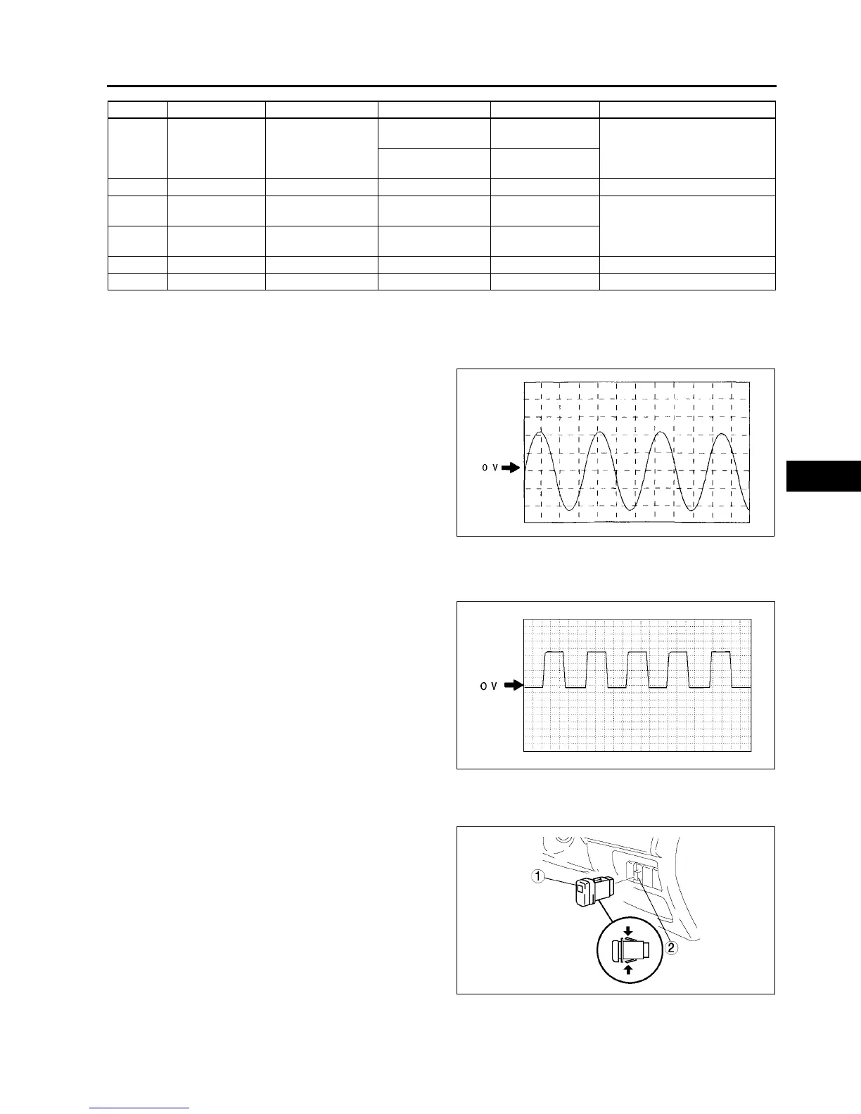
Vehicle speed output
•
• ABS/TCS HU/CM terminal: V( + ) AC ( - )
• Oscilloscope setting:
1 V/DIV (Y), 5 ms/DIV (X), DC range
• Vehicle condition: Driving 30 km/h (18.6 mph)
Note
• As vehicle speed increases, period of wave
shortens.
End Of Si e
TCS (DSC) OFF SWITCH REMOVAL/INSTALLATION
A6E692167650W02
1. Press the hooks of the TCS OFF switch and pull the switch out.
2. Disconnect the connector.
3. Install in the reverse order of removal.
End Of Si e
Y Brake switch Brake switch
Brake pedal is
depressed
1014
• Inspect related harness
Brake pedal is
released
Below 0.5
Z Power supply Ignition switch B+ • Inspect related harness
AA
Power supply
(Solenoid valve)
Battery B+
• Inspect related harness
AB
Power supply
(ABS motor)
Battery B+
AC Ground Ground 0 • Inspect related harness
AD Ground Ground 0 • Inspect related harness
Terminal Signal Connected to Test condition Voltage (V) Action
Z3U0413W201
Z3U0413W202
A6E6921W008