ON-BOARD DIAGNOSTIC [MULTIPLEX COMMUNICATION SYSTEM]
T143
T
PCM
1. Check the display of DTC U0121 and/or U0155, using the SST (WDS or equivalent). (See T142 DTC TABLE.)
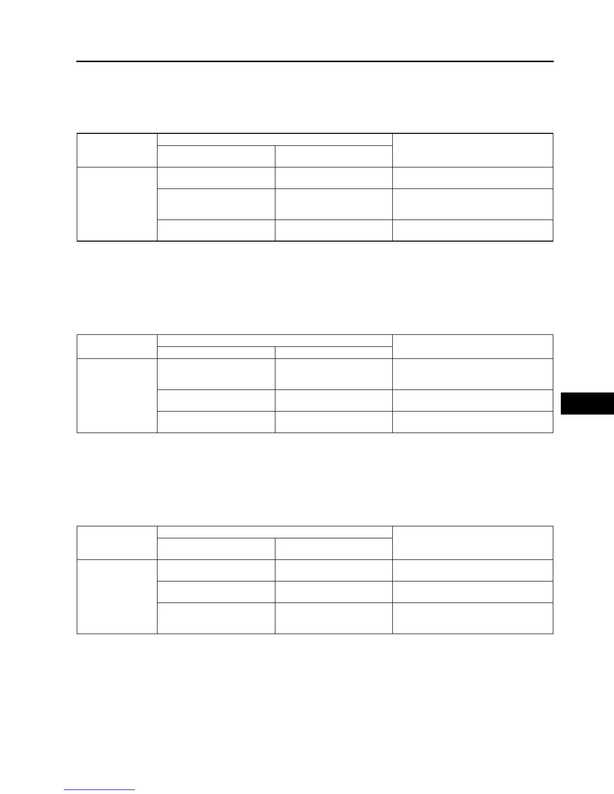
2. Referring to the following table, determine the malfunctioning part of the CAN system.
X: Normal
: Communication error
ABS/TCS HU/CM or DSC HU/CM
1. Accec and monitor the PCM MSG and IC MSGof PID using the SST (WDS or equivalent).
2. Referring to the PID/DATA MONITOR, confirm the display status of the PID. (See T142 PID/DATA MONITOR
TABLE.)
3. Referring to the following table, determine the malfunctioning part of the CAN system.
X: Normal
: Communication error
Instrument Cluster
1. Accec and monitor the PCM MSG and ABS MSG of PID using the SST (WDS or equivalent).
2. Referring to the PID/DATA MONITOR, confirm the display status of the PID. (See T142 PID/DATA MONITOR
TABLE.)
3. Referring to the following table, determine the malfunctioning part of the CAN system.
X: Normal
: Communication error
End Of Sie
Module
Communication status
Malfunction location
•
••
• ABS (ABS/TCS) HU/CM
•
••
• DSC HU/CM
Instrument cluster
PCM
• Wiring harness A
• PCM
X
• Wiring harness B
• ABS (ABS/TCS) HU/CM
• DSC HU/CM
X
• Wiring harness C
• Instrument cluster
Module
Communication status
Malfunction location
PCM Instrument cluster
• ABS (ABS/TCS)
HU/CM
• DSC HU/CM
• Wiring harness B
• ABS (ABS/TCS) HU/CM
• DSC HU/CM
X
• Wiring harness A
• PCM
X
• Wiring harness C
• Instrument cluster
Module
Communication status
Malfunction location
PCM
•
••
• ABS (ABS/TCS) HU/CM
•
••
• DSC HU/CM
Instrument cluster
• Wiring harness C
• Instrument cluster
X
• Wiring harness A
• PCM
X
• Wiring harness B
• ABS (ABS/TCS) HU/CM
• DSC HU/CM