F1–24
FUEL SYSTEM
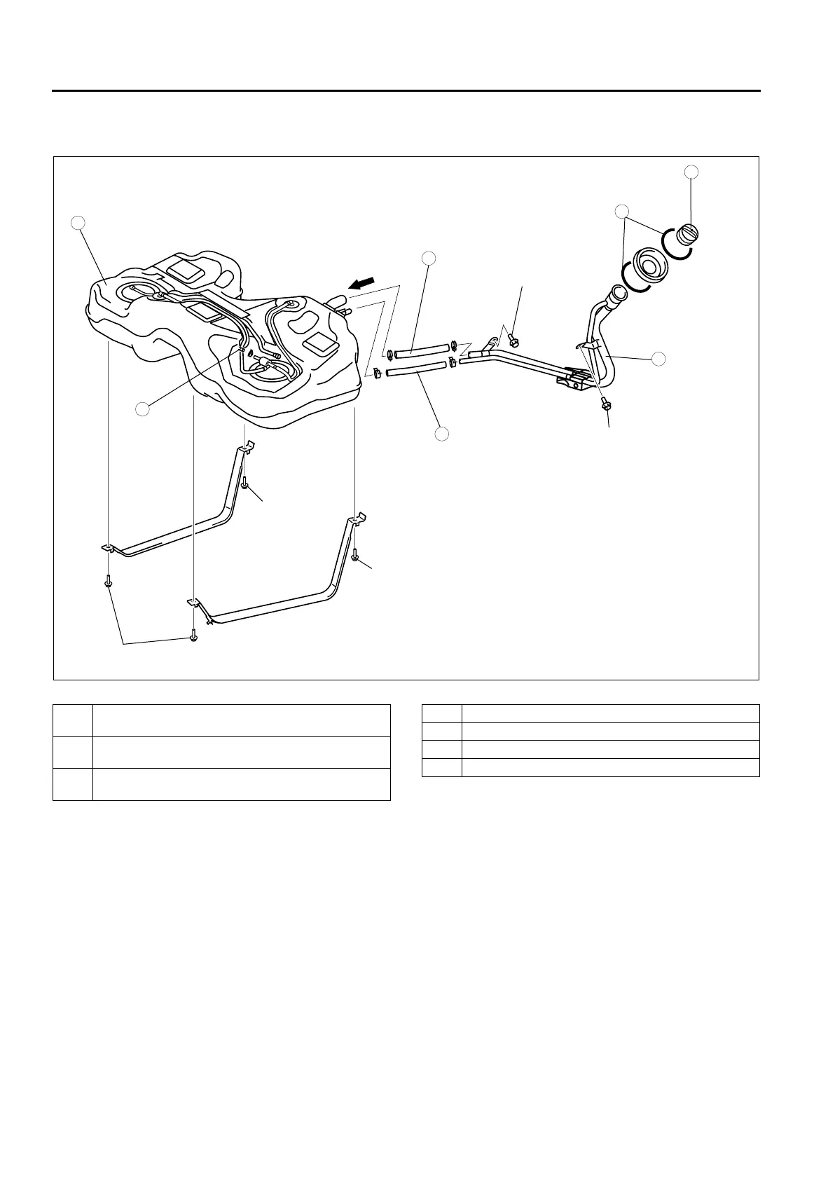
10. Remove in the order indicated in the table.
11. Install in the reverse order of removal.
12. Complete the “AFTER REPAIR PROCEDURE”.
.
44—60
{4.5—6.1, 33—44}
7
5
4
3
2
1
6
A
N·m {kgf·m, ft·lbf}
44—60
{4.5—6.1, 33—44}
44—60
{4.5—6.1, 33—44}
8.9—12.7 N·m
{91—120 kgf·cm, 79—110 in·lbf}
8.9—12.7 N·m
{91—120 kgf·cm, 79—110 in·lbf}
A6E39122008
1 Joint hose
(See F1–25 Joint Hose Installation Note)
2 Breather hose
(See F1–25 Breather Hose Installation Note)
3 Evaporative hose
(See F1–25 Evaporative Hose Installation Note)
4 Fuel tank
5 Fuel-filler pipe
6 C-ring
7 Filler cap
 Loading...