AUTOMATIC TRANSAXLE
K2–101
K2
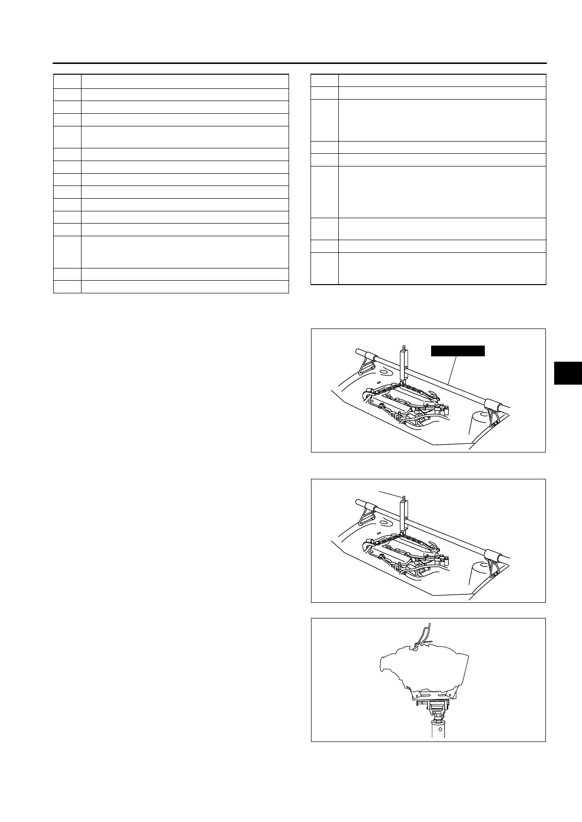
No.1 Engine Mount Bracket Removal Note
1. Support the engine using the SST before removing the No.1 engine mount.
2. Remove the No.1 engine mount.
Transaxle Removal Note
1. Loosen the part marked A and lean the engine
toward the transaxle.
2. Support the transaxle on a jack.
3. Remove the transaxle mounting bolts.
4. Remove the transaxle.
1O
2
sensor connector
2 Terminal component No.1, No.2 connector
3 TR switch connector
4 GND harness
5 Selector cable
(See K2–104 Selector Cable Installation Note)
6 Cable bracket
7 Oil hose
8 Transaxle mounting bolt (upper side)
9 Starter (See Section G)
10 Endplate cover
11 Lower arm (front, rear) ball joint (See Section R)
12 Damper fork
13 Tie-rod end ball joint
(See N–13 STEERING GEAR AND LINKAGE
(4WD) REMOVAL/INSTALLATION)
14 Stabilizer control link
15 Drive shaft (left side) (See Section M)
16 Drive shaft (right side) (See Section M)
17 Joint shaft (See Section M)
18 No.1 engine mount
(See K2–101 No.1 Engine Mount Bracket Removal
Note)
(See K2–103 No.1 Engine Mount Installation Note)
19 Crossmember bracket
20 Crossmember, steering gear (See Section R)
21 Torque converter installation nuts
(See K2–102 Torque Converter Nuts Removal
Note)
(See (SeeK2–102 Torque Converter Nuts
Installation Note)
22
No.4 engine mount
(See K2–103 No.4 Engine Mount Installation Note)
23 Transaxle mounting bolt (lower side)
24 Transaxle
(See K2–101 Transaxle Removal Note)
(See K2–102 Transaxle Installation Note)
49 E017 5A0
A6E5714W132
A
A6E5714W133
A6E5714W134
 Loading...