M–66
ELECTRONIC 4WD CONTROL SYSTEM
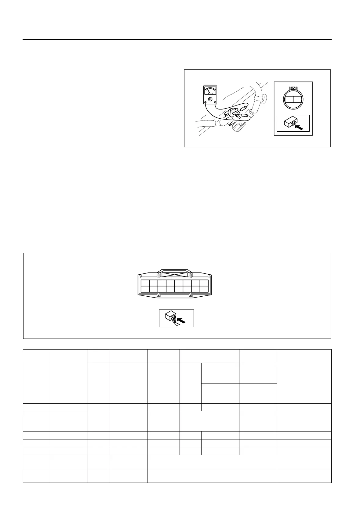
4WD SOLENOID INSPECTION
A6E632227100211
1. Disconnect the negative (-) battery cable.
2. Disconnect the 4WD solenoid connector.
3. Measure resistance between 4WD solenoid
connector terminals A and B.
• If the resistance is not within the specification,
replace the coupling unit.
Resistance
1.5—2.0 ohms
(Rear differential oil temperature at 20°C
{68°F})
4. Connect the 4WD solenoid connector.
5. Connect the negative (-) battery cable.
End Of Sie
4WD CONTROL MODURE INSPECTION
A6E632227100212
Note
• 4WD CM terminal voltage can vary depending on measuring conditions and vehicle aging, resulting in
misdiagnosis. Therefore, it is necessary to perform an overall inspection of the input/output systems and
4WD CM to determine which part is malfunctioning.
• With the 4WD CM connector connected, measure voltage by connecting the voltmeter negative (-) lead to
the body ground and positive (+) lead to each 4WD CM terminal.
1. Measure voltage or resistance at each 4WD CM terminal using a voltmeter and an ohmmeter.
• If not as specified, replace the 4WD CM.
Terminal Voltage List (Reference)
A
B
A6J63222103
Terminal Signal
Input/
output
Connected
to
Measuring
item
Test condition
Voltage (V)/
Continuity
Inspection location
in case of failure
A
Differential oil
temperature
sensor signal
Input
Differential oil
temperature
sensor
Voltage
Ignition
key
ON
Differential oil
temperature
20°C {68°F}
3.0
• Inspect
differential oil
temperature
sensor
• Inspect related
harness
Differential oil
temperature
60°C {140°F}
1.4
B ——— ——— — —
C
Differential oil
temperature
sensor GND
—
Differential oil
temperature
sensor
Continuity Any condition Yes
• Inspect related
harness
D ——— ——— — —
E ——— ——— — —
F ——— ——— — —
GCAN-H
Input/
output
— Perform measurement during DTC inspection. —
HCAN-L
Input/
output
— Perform measurement during DTC inspection. —
A
B
C
D
E
F
G
H
I
J
K
L
M
N
O
P
A6J63222104