ELECTRONIC 4WD CONTROL SYSTEM
M–67
M
End Of Sie
4WD CONTROL MODURE REMOVAL/INSTALLATION
A6E632227100213
1. Disconnect the negative (-) battery cable.
2. Remove the lower panel.
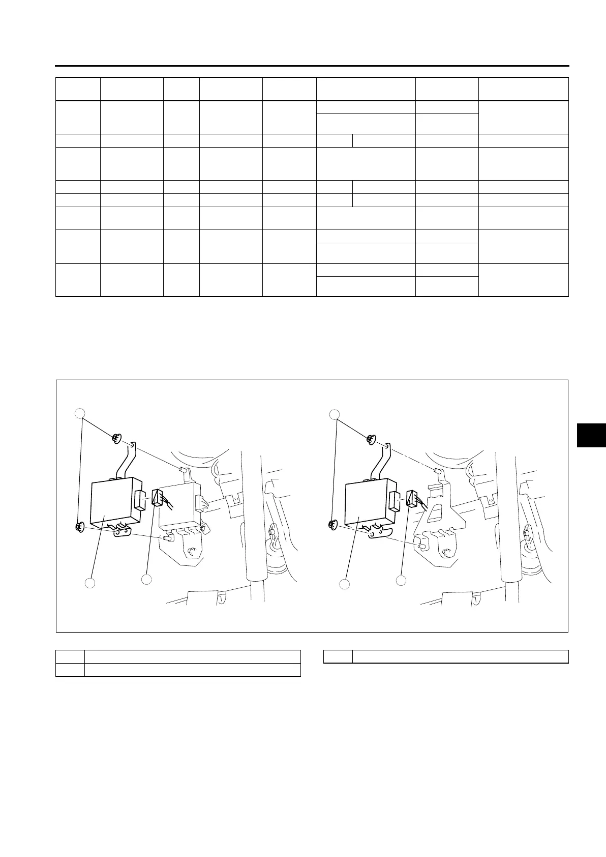
3. Remove in the order indicated in the table.
4. Install in the reverse order of removal.
.
End Of Sie
I
Power supply
(Ignition
switch)
Input Ignition key Voltage
Ignition key ON B+ • Inspect fuse
• Inspect related
harness
Ignition key OFF 1.0 or below
J ——— ——— — —
K
Power supply
(Main)
Input Battery Voltage Any condition B+
• Inspect fuse
• Inspect related
harness
L ——— ——— — —
M ——— ——— — —
N Ground — Ground Voltage Any condition 0
• Inspect related
harness
O
4WD solenoid
(+)
Output 4WD solenoid Voltage
Ignition key ON B+ • 4WD solenoid
• Inspect related
harness
Ignition key OFF 1.0 or below
P
4WD solenoid
(-)
Output 4WD solenoid Voltage
Ignition key ON B+ • 4WD solenoid
• Inspect related
harness
Ignition key OFF 1.0 or below
Terminal Signal
Input/
output
Connected
to
Measuring
item
Test condition
Voltage (V)/
Continuity
Inspection location
in case of failure
3
1
2
3
1
2
7.8—10.8 {0.8—1.1, 5.6—7.9}
N·m {kgf·m, ft·lbf}
7.8—10.8 {0.8—1.1, 5.6—7.9}
L.H.D.
R.H.D.
A6E63222105
1 Connector
2Nut
34WD CM