P–18
DYNAMIC STABILITY CONTROL
K
H
RR wheel-speed
RR wheel-
speed sensor
Vehicle is stopped 0 (AC)
• Inspect related harness
• Inspect wheel-speed
sensor
• Inspect using the wave profile.
(See P–19 Inspection Using An
Oscilloscope (Reference))
M
I
RF wheel-speed
RF wheel-
speed sensor
Vehicle is stopped 0 (AC)
• Inspect related harness
• Inspect wheel-speed
sensor
• Inspect using the wave profile.
(See P–19 Inspection Using An
Oscilloscope (Reference))
Q
N
LR wheel-speed
LR wheel-speed
sensor
Vehicle is stopped 0 (AC)
• Inspect related harness
• Inspect wheel-speed
sensor
• Inspect using the wave profile.
(See P–19 Inspection Using An
Oscilloscope (Reference))
G Battery (IG) Ignition switch Ignition switch ON B+
• Inspect related harness
• Inspect ignition switch
L Brake switch Brake switch
When brake pedal is
depressed
10—14
• Inspect related harness
• Inspect brake switch
O
Lateral-G
(lateral-G signal)
Combine
sensor
Vehicle is stopped 2.2—2.8
• Inspect related harness
• Inspect combine sensor
Left cornering
Fluctuation
between
2.5—4.0 V
Right cornering
Fluctuation
between
1.0—2.5 V
P
Combine sensor
power output
Combine
sensor
Ignition switch ON 4.75—5.25
• Inspect related harness
• Inspect combine sensor
R
Steering angle
(ground)
Steering angle
sensor
— Below 1.0
• Inspect related harness
• Inspect steering angle
sensor
S Combine sensor
Combine
sensor
— 3.5—5.0
• Inspect related harness
• Inspect combine sensor
T
Yaw rate
(yaw rate signal)
Combine
sensor
Vehicle is stopped 2.2—2.8
• Inspect related harness
• Inspect yaw rate sensor
Right cornering
Fluctuation
between
2.5—4.62 V
Left cornering
Fluctuation
between
2.5—0.33 V
U
Steering angle
(neutral signal)
Steering angle
sensor
Steering position:
center position 25°—29°
Below 1.0
• Inspect related harness
• Inspect steering angle
sensor
Except above condition Approx. 4
V
Forward-G
(forward-G signal)
Combine
sensor
Vehicle is stopped 2.2—2.8
• Inspect related harness
• Inspect combine sensor
Acceleration
Fluctuation
between
2.5—4.0 V
Deceleration
Fluctuation
between
1.0—2.5 V
W
Steering angle
(steering angle
signal 2)
Steering angle
sensor
• Inspect using the wave profile.
(See P–19 Inspection Using An
Oscilloscope (Reference))
• Inspect related harness
• Inspect steering angle
sensor
X
Steering angle
(steering angle
signal 1)
Steering angle
sensor
• Inspect using the wave profile.
(See P–19 Inspection Using An
Oscilloscope (Reference))
• Inspect related harness
• Inspect steering angle
sensor
Y
Combine sensor
(ground)
Combine
sensor
— Below 1.0
• Inspect related harness
• Inspect combine sensor
AA DSC OFF switch
DSC OFF
switch
When switch is pressed Below 1.0
• Inspect related harness
• Inspect DSC OFF switch
When switch is not pressed B+
AB OBD
KLN terminal of
DLC-2
It cannot be determined with terminal
voltage whether the condition is good or bad
because advanced function diagnostic
output is performed with serial
communication. Inspect with service codes.
• Inspect related harness
• Inspect DSC HU/CM
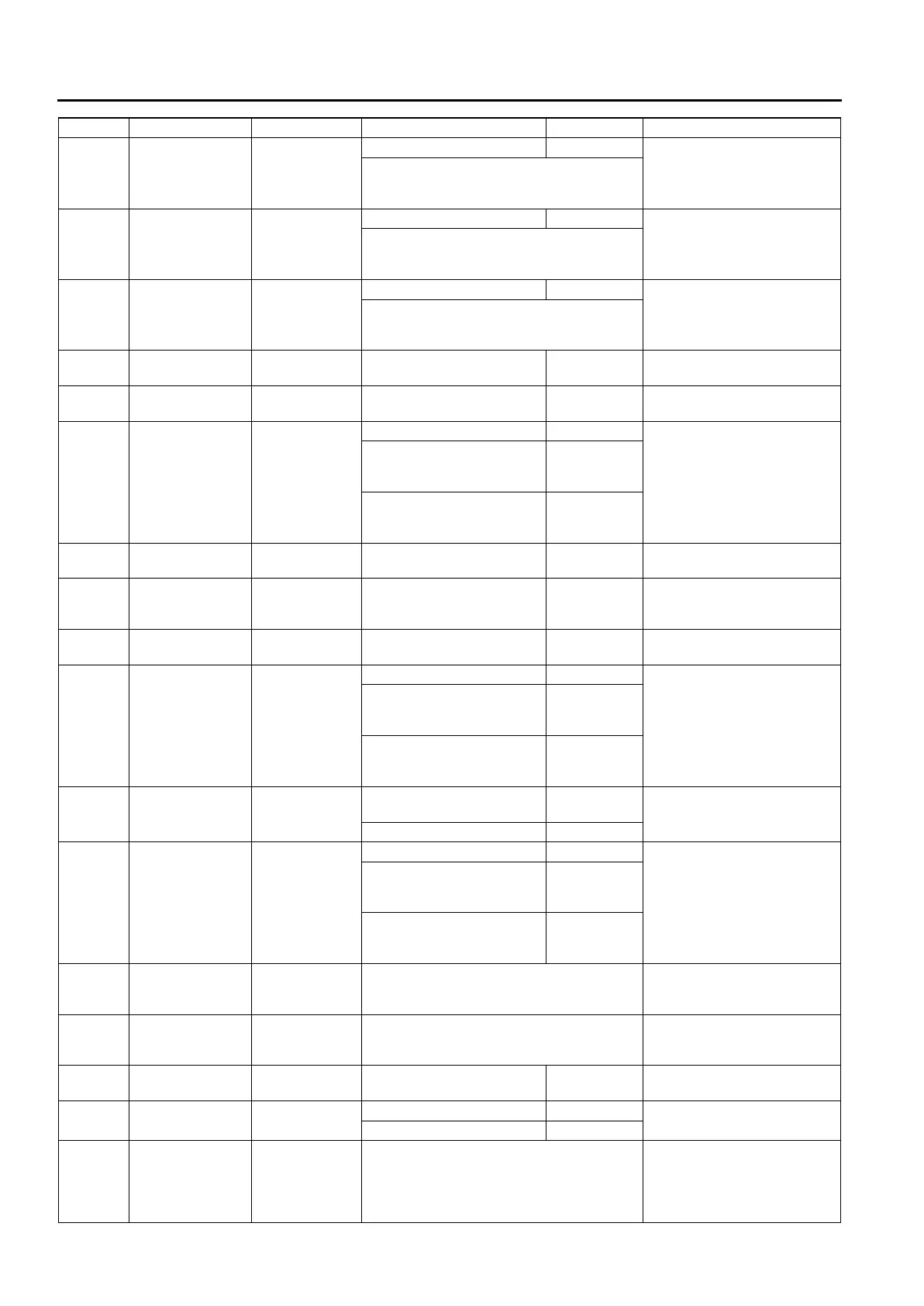
Terminal Signal Connected to Test condition Voltage (V) Action
 Loading...