DYNAMIC STABILITY CONTROL
P–19
P
*
: Used for vehicle manufacturing, not used for DSC.
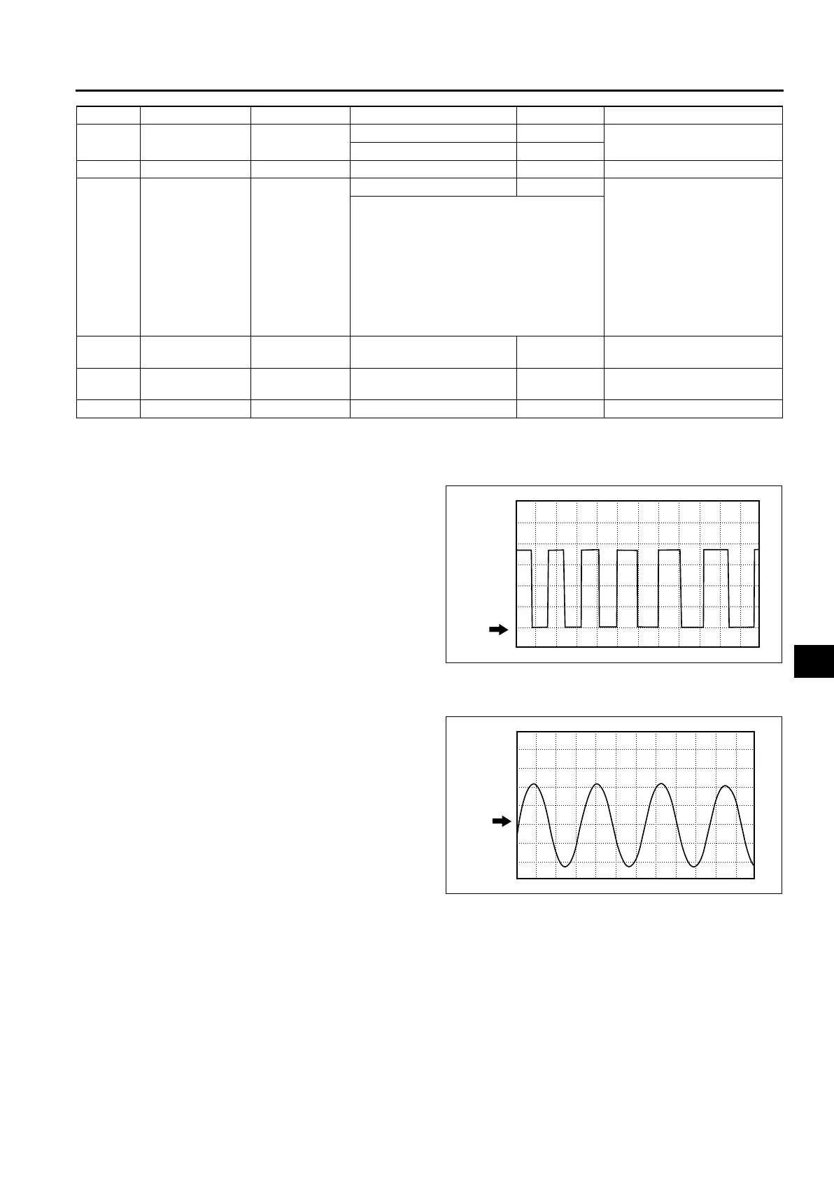
Inspection Using An Oscilloscope (Reference)
Steering angle (steering angle signal 1 and 2)
• DSC HU/CM terminal:
Steering angle signal 2: W (+) — R (-)
Steering angle signal 1: X (+) — R (-)
• Oscilloscope setting:
1 V/DIV (Y), 25 ms/DIV (X), DC range
• Vehicle condition: Rotating steering wheel at one
revolution per second
Note
• As steering wheel rotation speed increases,
period of wave shortens.
• As for shape of steering angle signals 1 and
2, the phase is different.
Wheel speed
• DSC HU/CM terminal:
RF: M (+) — I (-)
RR: K (+) — H (-)
LF: F (+) — J (-)
LR: Q (+) — N (-)
• Oscilloscope setting:
1 V/DIV (Y), 2 ms/DIV (X), AC range
• Vehicle condition: Driving 30 km/h (18.6 mph)
Note
• As vehicle speed increases, period of wave
shortens.
• If there is malfunctioning in the sensor rotor,
wave profile warps.
AC
Auto cruise set
signal output
Auto cruise unit
When auto cruise is ON Below 1.0
• Inspect related harness
• Inspect DSC HU/CM
When auto cruise is OFF B+
AD —— — — —
AE
Vehicle speed
output
• Audio unit
• Wiper and
washer
switch
• Car-navigatio
n unit
• Auto
leveling
control unit
• Cruise
actuator
Vehicle is stopped 0
• Inspect related harness
• Inspect front wheel-speed
sensor
• Inspect using the wave profile.
(See P–19 Inspection Using An
Oscilloscope (Reference))
AF CAN-L ——
No need to
check
—
AG CAN-H ——
No need to
check
—
AH —— — — —
Terminal Signal Connected to Test condition Voltage (V) Action
0 V
A6E6921W014
0 V
A6E6921W013
 Loading...