T–4
MULTIPLEX COMMUNICATION SYSTEM
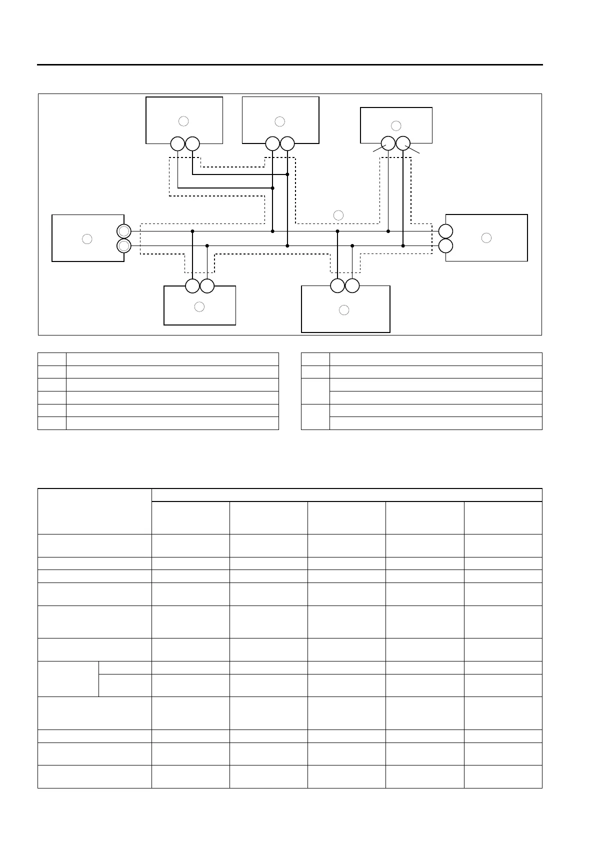
SYSTEM WIRING DIAGRAM
A6E811155430203
.
End Of Sie
CAN SIGNAL-CHART
A6E811155430204
OUT: Output (sends signal)
IN: Input (receives signal)
1
2
6
7
3
8
4
5
R
O
AF AG
H
G
2M
2J
2W
2X
9
10
CAN_L
CAN_H
A6E81111102
1PCM
2 DSC HU/CM (with DSC)
3 ABS (ABS/TCS) HU/CM (with ABS (ABS/TCS))
4 Data link connector-2
5 Instrument cluster
6 TCM (JA5AX-EL)
7 4WD control module (4WD)
8Twist pair
9 2R (except MZR-CD (RF Turbo))
39 (MZR-CD (RF Turbo))
10 2U (except MZR-CD (RF Turbo))
13 (MZR-CD (RF Turbo))
Signal
Multiplex module
PCM TCM
ABS (ABS/TCS)
HU/CM or
DSC HU/CM
4WD control
module
Instrument
cluster
Accelerator pedal position
(MZR-CD (RF Turbo))
OUT IN IN – IN
Air induction type OUT – IN ––
ATF temperature IN OUT –––
AT warning light conditions
(JA5AX-EL)
IN OUT ––IN
Battery reconnection
(except MZR-CD (RF
Turbo))
OUT IN –––
Brake system configuration
(EBD/ABS/TCS/DSC)
IN – OUT – IN
Brake system
status
ABS IN – OUT ––
EBD/ABS/
TCS/DSC
––OUT IN IN
Brake system warning light
conditions (brake fluid level
sensor)
––IN – OUT
Country OUT – IN ––
Coupling torque (with
DSC)
––IN OUT –
Coupling torque request
(with DSC)
––OUT IN –









 To Next Page