F1–10
FUEL SYSTEM
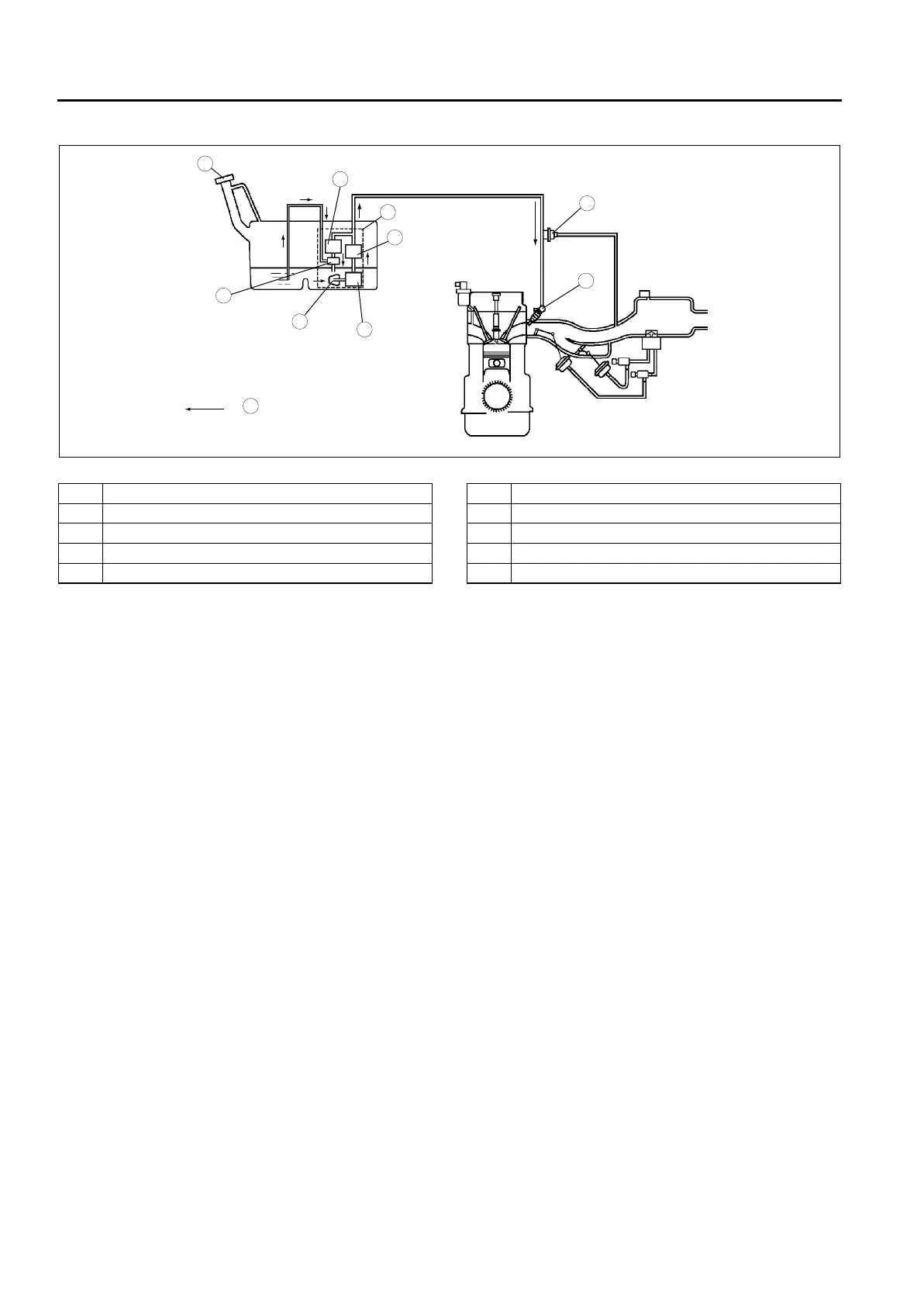
SYSTEM DIAGRAM
A6E391201006203
.
End Of Sie
FUEL PUMP (TRANSFER)
A6E391213350201
Function
• The fuel tank for 4WD is saddle type. Fuel in the fuel gauge sender sub-unit side (right side) is pumped to the
left side of the fuel tank using the fuel pump (transfer).
Structure
• The fuel pump (transfer) is integrated into the fuel pump unit and it cannot be separately disassembled.
• The fuel pump (transfer) is composed of a relief valve and fuel jet pump.
8
7
5
4
3
6
1
2
:
9
10
A6E39122002
1 Filler cap
2 Pressure regulator
3 Fuel pump (transfer)
4 Fuel filter (high-pressure)
5Fuel pump
6 Fuel filter (low-pressure)
7 Fuel pump unit
8 Pulsation damper
9 Fuel injector
10 Fuel flow