OILDYNE TRIM PUMP
SERVICE MANUAL NUMBER 28
90-863160 MAY 2000 Page 5A-45
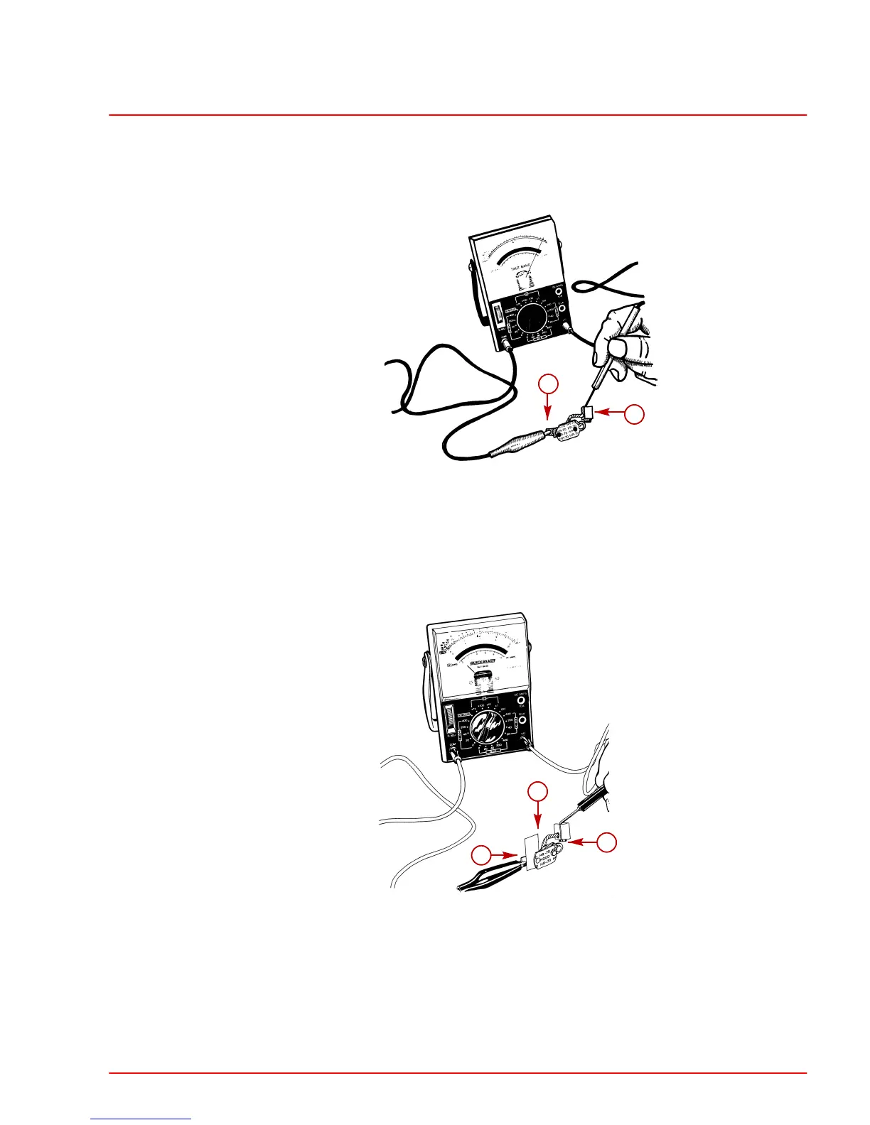
Thermal Switch Continuity Test
1. Connect the ohmmeter between the spade connector and the brush lead.
22631
b
a
a-Thermal Switch Spade Connector
b-Brush Lead
2. Zero ohms indicated (full continuity) - Proceed to next step.
Zero ohms not indicated (no continuity) - Replace thermal switch.
3. Insert an insulator (piece of paper) between the contact points on the ohmmeter (be-
tween spade connector and brush lead).
22649
b
c
a
a-Thermal Switch Spade Connector
b-Brush Lead
c-Insulator (Piece Of Paper)
4. Zero ohms indicated (full continuity) -Replace thermal switch.
Zero ohms not indicated (no continuity) - Thermal switch OK.
5. Remove the insulator from between the contact points on the thermal switch. Clear all
material away from the points.
 Loading...


