POWER STEERING
SERVICE MANUAL NUMBER 28
90-863160 MAY 2000 Page 6A-35
Selection
TIE BAR CHART
For Dual Installations with Steering Cable Attached to Starboard Power Package
*16” to 30” 92020A1
*30” to 46” 92020A2
46” to 62” 92020A3
* If centerline distance is the same as maximum figure, use next larger size tie bar.
TIE BAR CHART
For Dual Installations with Steering Cable Attached to Port Power Package
*28” to 37-1/2” 96708A4
* 37-1/2” to 55” 96708A5
55” to 72” 96708A6
* If centerline distance is the same as maximum figure, use next larger size tie bar.
Installation
DUAL INSTALLATIONS WITH STEERING CABLE ATTACHED TO STARBOARD POWER PACKAGE
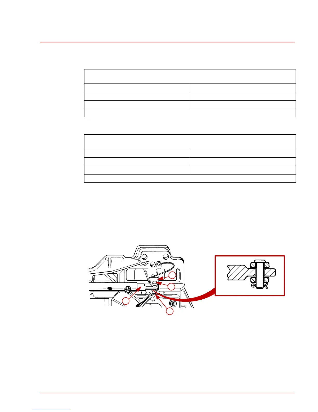
1. Attach fixed bar end to steering lever, using clevis pin and cotter pin. Spread cotter pin
ends.
22079
22211
a
b
c
d
a-Fixed End
b-Steering Lever
c-Clevis Pin
d-Cotter Pin
2. Position sterndrive units as desired and turn adjustable end out (if necessary) to align
hole in bar end with holes in steering lever and piston rod end clevis.
3. Turn adjustable end out 3 to 4 turns from this position.
4. Apply Loctite 277 to exposed tie bar threads; then turn tie bar back in (3 to 4 turns) to
previously aligned position.
 Loading...


