REMOVAL, INSTALLATION AND ADJUSTMENTS SERVICE MANUAL NUMBER 28
Page 2A-12 90-863160 MAY 2000
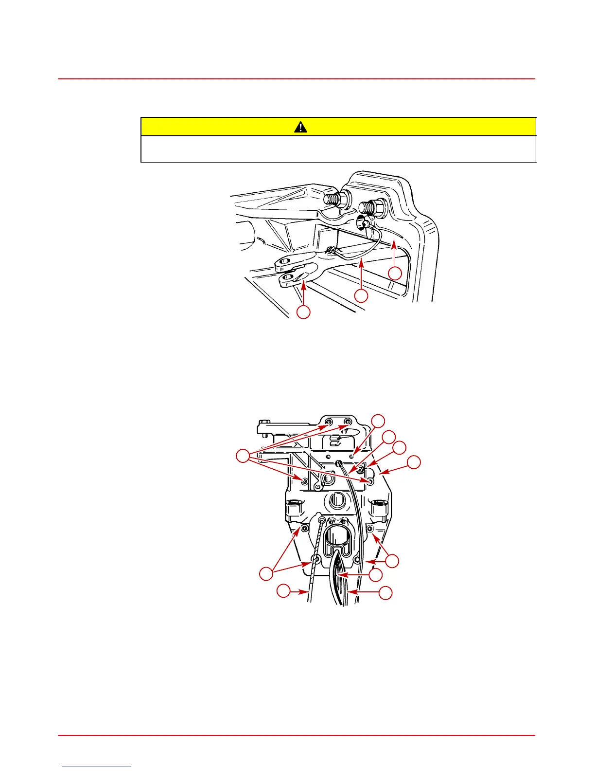
Transom Assembly Installation
CAUTION
Avoid continuity wire failure. Position the steering lever ground wire as shown or
the wire may fatigue and break.
22028
a
b
c
a-Steering Lever
b-Transom Plate
c-Continuity Wire
1. Install the transom assembly. Tighten locknuts evenly, starting from the center and
working outward. Torque to 23 lb-ft (31 Nm).
73902
a
c
f
a
e
d
g
h
a
b
a-Locknuts and Flat Washers
b-Power Trim Hoses
c-MerCathode Wires
d-Continuity Wire
e-Trim Limit And Trim Position Sender Wires
f-Grounding Bolt
g-Speedometer Connection
h-Shift Cable
 Loading...


