Assembly - continued
17. Attach the valve bushing unit to the heated body using socket head cap
screws. Torque to 7 Nm (5 ft-lb). See Figure 11-18.
Figure 11-18 Bolt valve bushing unit to heated body
IMPORTANT
Prior to step 18, ensure that none of the O-ring grooves have sharp edges.
A small amount of lubrication applied to all outside faces of the seals prior
to O-ring installation will make the procedure easier.
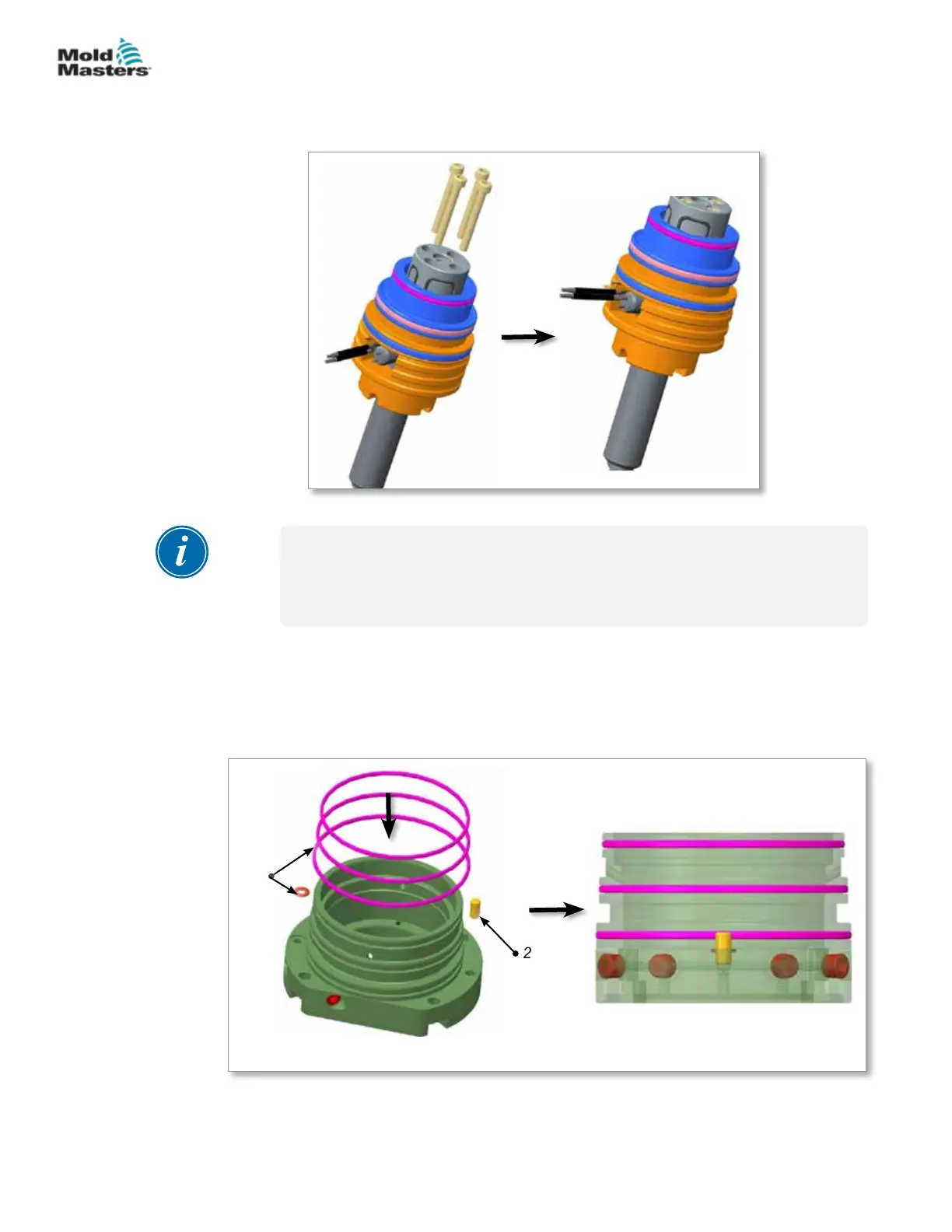
18. As shown in the General Assembly drawing, install the O-rings into the
grooves on the outer body. Carefully push the O-rings into the grooves
using your nger. Ensure the O-rings are rmly seated in the groove. See
Figure 11-19.
19. Install the dowel pin onto the outer body. See Figure 11-19.
1. O-rings 2. Dowel pin
1
2
Figure 11-19 Install O-rings and dowel pin
11-12
© 2020 Mold-Masters (2007) Limited. All Rights Reserved.
SLIMSTACK ACTUATOR
Hot Runner User Manual