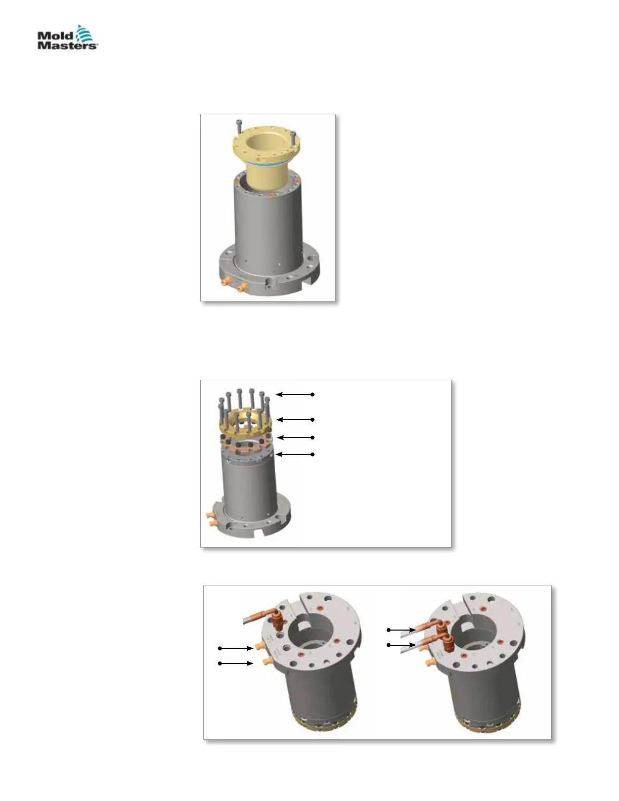
12. Install the cylinder top into the outer cylinder, making sure that the O-rings
are not disturbed from their positions. Align it with the anti-rotation dowel.
13. Insert the screws and torque them to 7 N∙m (5 lbf-ft).
14. Place the insulation plate on the cylinder body, and install the support
sleeves.
Place the cover plate on the insulation plate.
Insert the socket head cap screws and tighten them to a torque of 14 N∙m
(10 lbf-ft).
1. Insulation plate
2. Sleeve
3. Cover plate
4. Socket head cap screws
1
2
3
4
15. Insert the actuator connection hose ttings into the supply ports on the
bottom of the unit assembly.
1
3
2
4
1. Cooling in
2. Cooling out
3. Gate open
4. Gate close
17-16
© 2020 Mold-Masters (2007) Limited. All Rights Reserved.
ACCU-LINE™
Hot Runner User Manual


 To Next Page