R&S
®
ZVA / R&S
®
ZVB / R&S
®
ZVT GUI Reference
Trace Menu
Operating Manual 1145.1084.12 – 30 114
Measurements at Two Different Frequencies (for R&S ZVA and R&S ZVT
Analyzers)
The More Ratios and More Wave Quantities dialogs provide the wave quantities a1, b1... These wave
quantities are measured at the common receiver frequency, which is equal for all ports: If no frequency-
converting mode is active, the common receiver frequency is equal to the stimulus frequency of the NWA
source (channel base frequency f
b
).
With option R&S ZVA-K9, Arbitrary Generator and Receiver Frequencies, the network analyzer provides
an additional set of "primed" wave quantities a'1, b'1..., to be measured at fixed, but port-specific
frequency offsets from the common receiver frequency. Primed wave quantities can also be used to
calculate ratios.
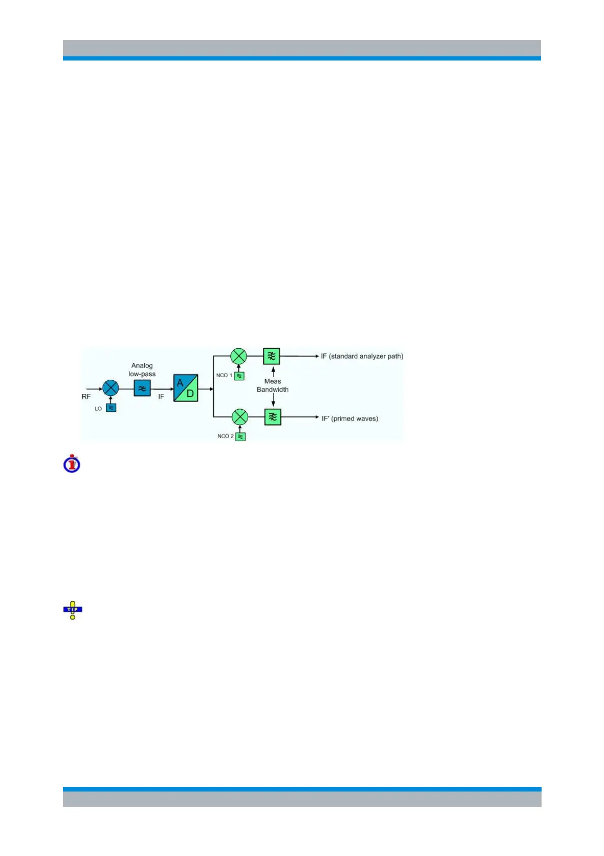
The basic and the primed results are measured in two different analyzer paths. The two signals are
separated in the digital part of the receiver, after down-conversion of the RF input signal in the first mixer,
a lowpass filter stage, and analog/digital conversion. The digital paths contain mixer stages with two
independent numerically controlled oscillators NCO 1 and NCO 2. Each of the NCOs converts one signal
component to the analyzer frequency.
The port-specific frequency offset between primed and unprimed waves can be set in the Receiver section
of the Port Configuration dialog (
Freq a', b').
Measurement application, bandwidth considerations
The second analyzer and the quantities a'1, b'1, a's1, a'c1,... are suited for a comparison of two signals or
signal components at different frequencies (two tone signals). Typical examples are:
Measurement of intermodulation products
Adjacent Channel Power (ACP) measurements
The maximum frequency offset between primed and unprimed waves is limited by the cutoff frequency of
the analog lowpass filer. The minimum frequency offset is determined by the bandwidth of the digital IF
filters (Channel Power Bandwidth Average Meas Bandwidth). It is recommended to use IF filters with
high selectivity.
The port-specific frequency offset extends the receiver frequency conversion in the Receiver
Frequency dialog, which is equal for all analyzer ports.
In remote control, it is possible to define an additional port-specific offset to the basic frequencies; see
remote control commands below. The additional offset is not displayed in the Port Configuration dialog.
The total frequency offset between primed and basic wave quantities is equal to (
Freq a', b' –
Freq a,
b).
SENSe<Ch>:FREQuency<Pt>:OFFSet:PWAVes
SENSe<Ch>:FREQuency<Pt>:OFFSet:WAVes