R&S
®
ZVA / R&S
®
ZVB / R&S
®
ZVT GUI Reference
Channel Menu
Operating Manual 1145.1084.12 – 30 294
Control, AGC). The A/D converter is always operated at optimum input level.
The following settings accelerate the measurement:
Low Dist(ortion) corresponds to a small IF gain (i.e. a lower internal A/D converter input level).
This setting allows for a high RF overdrive reserve and is appropriate for high RF input levels.
Low Noise corresponds to a large IF gain (i.e. a higher internal A/D converter input level). This
setting increases the dynamic range and is appropriate for low RF input levels.
The Low Dist or Low Noise settings are appropriate whenever the characteristics of the input path must be
constant, e.g. because:
Interfering signal contributions originating from the receiver (noise, nonlinear contributions) must
not change during the measurement.
A large interfering signal in the vicinity of the measured signal must not overdrive the receiver.
[SENSe<Ch>:]LOMeasure
[SENSe<Ch>:]LOReference
[SENSe<Ch>:]FREQuency:STARt?
[SENSe<Ch>:]FREQuency:STOP?
[SENSe<Ch>:]SWEep:CW|FIXed?
[SENSe<Ch>:]CORRection:POWer[:STATe]
[SENSe<Ch>:]POWer:ATTenuation
[SENSe<Ch>:]POWer:IFGain:MEASure
[SENSe<Ch>:]POWer:IFGain:REFerence
Converted Frequencies (R&S ZVA and R&S ZVT)
In the Source and Receiver sections of the Port Configuration table, it is possible to convert the source
and receiver frequency ranges (for frequency sweeps) or CW frequencies (for power, time and CW Mode
sweeps) in order to perform measurements on frequency-converting DUTs. The source frequency is port-
specific whereas the receiver frequency must be the same at all ports.
Test ports 1 and 2 and test ports 3 and 4 are supplied by a common generator (see block diagrams in
the data sheet). If the RF signal is simultaneously fed to two coupled ports (i.e. if Gen is switched on so
that at least one signal source is permanent), the port frequencies must be the same. For normal
measurements (Gen switched off), this restriction does not apply because there is only one source port
per partial measurement.
The frequency formula for a permanent signal source is also used for the second (coupled) test port.
On R&S ZVA67 and R&S ZVA24/40 network analyzers with four ports and four generators (order nos.
1145.1110.28/48), all four ports have independent internal sources, and the aforementioned restrictions
do not apply.
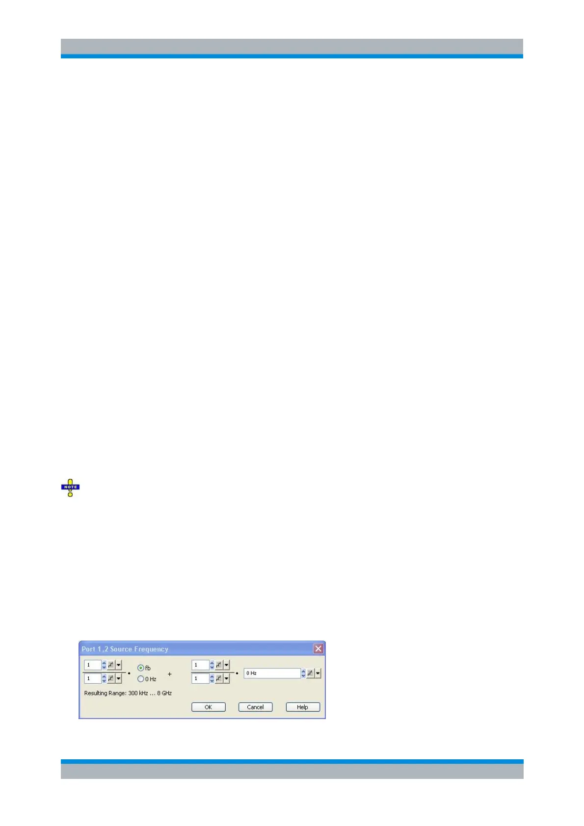
The port frequencies are calculated as a multiple of the stimulus frequency f
b
plus an offset. The
coefficients of the linear transformation between f
b
and the port frequencies are entered in dialogs of the
following type: