R&S
®
ZVA / R&S
®
ZVB / R&S
®
ZVT GUI Reference
Trace Menu
Operating Manual 1145.1084.12 – 30 159
Max Hold On enables or disables the max hold (peak hold) function for the active trace.
Min Hold On enables or disables the min hold function for the active trace.
Restart Hold restarts the max hold (peak hold) or min hold function for the active trace, discarding
the old maximum or minimum measurement results.
Restart Hold All restarts the max hold (peak hold) or min hold function for all traces with active
max hold or min hold function.
Linearity Deviation opens a submenu to compensate the active trace for the average slope and
response value in order to show the deviation from linearity.
Many of the functions of the Trace Funct menu act on the active trace. Data traces and the associated
memory traces share many of their properties; see coupling of memory traces.
Data -> Mem
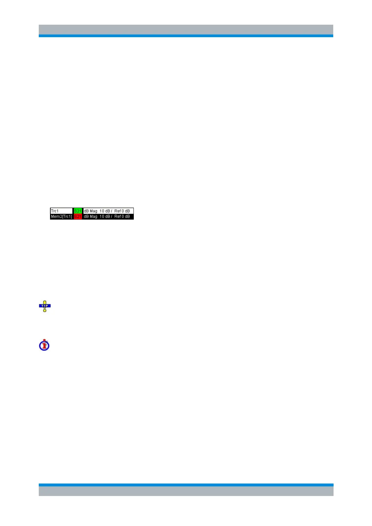
Stores the current state of the active trace as a memory trace. The memory trace is displayed in the active
diagram area with another color, and its properties are indicated in the trace list:
Memory traces are named Mem<n>[<Data_Trace>] where <n> counts all data and memory traces in the
active setup in chronological order, and <Data_Trace> is the name of the associated data trace. Trace
names can be changed in the Trace Manager dialog.
The exact function of Data -> Mem depends on the number of memory traces associated to the active
data trace:
If no memory trace is associated with the active trace, a new memory trace is generated.
If several memory traces are associated with the active trace, the current measurement data
overwrites the last generated or changed memory trace.
To store the current measurement data to a new memory trace (without overwriting an existing
memory trace), or select and overwrite a particular memory trace, use the -> Mem dialog. You can also
create multiple memory traces using the Import Data dialog. Notice that it is not possible to store Max.
Hold traces to memory.
Coupling of data and memory traces
When a memory trace is generated from a data trace, it is displayed in the same diagram area and
inherits all channel and trace settings from the data trace.
The following display settings of a data trace and the associated memory traces are fully coupled.
Changing a property of one trace affects the properties of all other traces.
All settings in the Trace – Format menu
All settings in the Trace – Scale menu
Selection of the measured quantity (Trace – Measure) is possible for the data trace but disabled for the
memory traces.
Channel settings made for a memory trace act on the associated data trace. Some of the channel settings
for a data trace (e.g. the Stimulus range) also affect the display of the memory traces.