R&S
®
ZVA / R&S
®
ZVB / R&S
®
ZVT GUI Reference
Trace Menu
Operating Manual 1145.1084.12 – 30 211
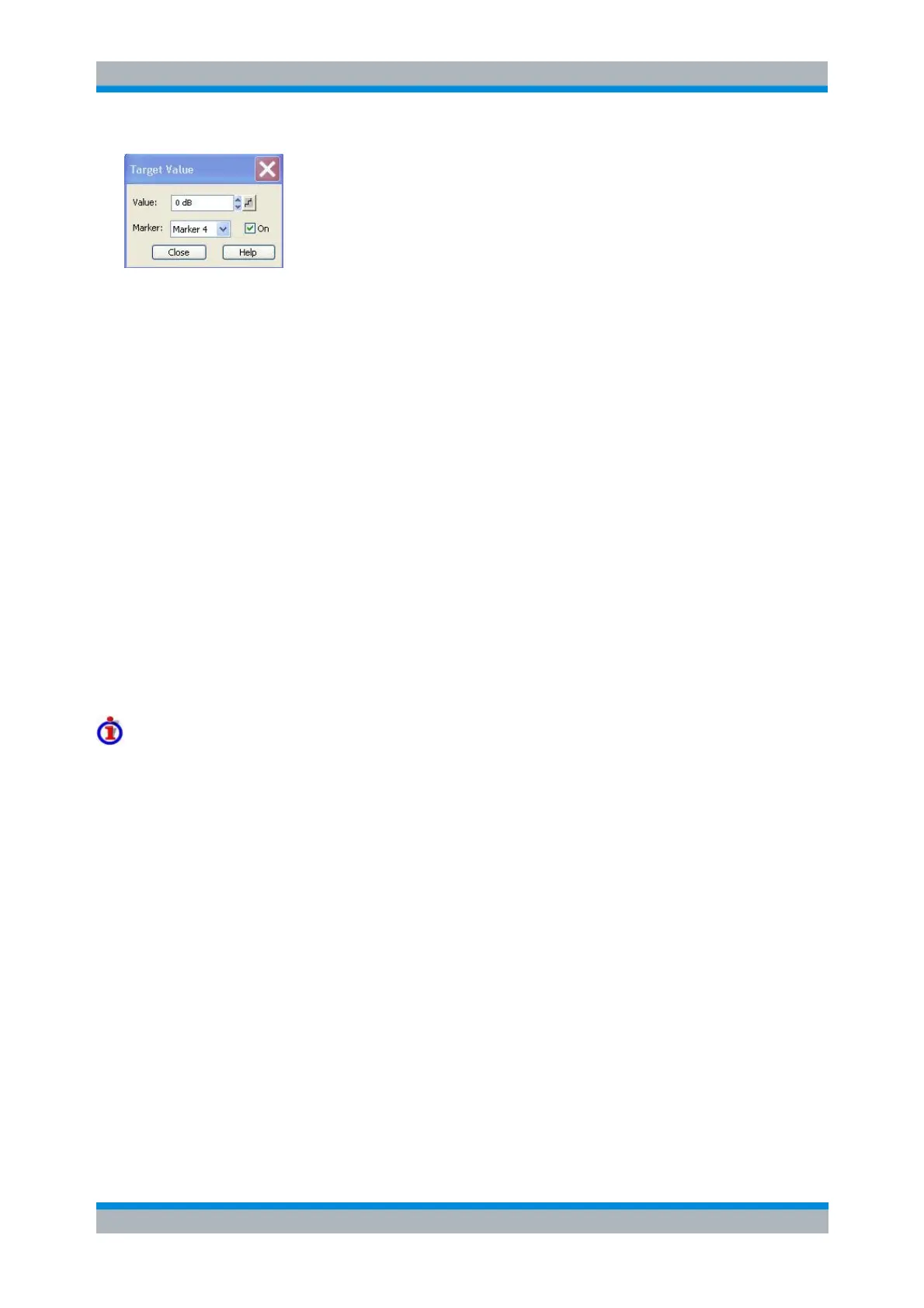
It is possible to define up to ten different target values for each trace and assign them to the markers no. 1
to 10. The input fields in the Target Search dialog are used to select the markers and define the
associated search ranges:
Marker selects one of the ten markers that can be assigned to the trace. If a selected marker does
not exist, it is created as soon as On is checked. A created marker is displayed in the center of the
search range.
Value selects the target value to be assigned to the selected marker. The target Value is entered
with the unit of the active trace.
CALCulate<Chn>:MARKer<Mk>:TARget
Search Range...
Opens the Search Range Dialog to confine the target search to a subrange of the sweep.
Bandfilter
Opens a submenu to search for trace segments with a bandpass or bandstop shape and determines
characteristic filter parameters.
Bandfilter search and filter parameters
Bandpass and bandstop regions can be described with the same parameter set:
A bandpass region contains a local maximum around which the magnitude of the trace falls off by
more than a specified x dB Bandwidth.
A bandstop region contains a local minimum around which the magnitude of the trace increases
by more than a specified x dB Bandwidth.
The analyzer locates bandpass and bandstop regions and determines their position (Center frequency)
and shape (Bandwidth, LBE, UBE, Quality factor Q; see Show Results). For a meaningful definition of the
x dB Bandwidth criterion, the trace format must be dB Mag.