R&S
®
ZVA / R&S
®
ZVB / R&S
®
ZVT GUI Reference
Trace Menu
Operating Manual 1145.1084.12 – 30 217
CALCulate<Chn>:MARKer<Mk>:FUNCtion:DOMain:USER
CALCulate<Chn>:MARKer<Mk>:FUNCtion:DOMain:USER:STARt
CALCulate<Chn>:MARKer<Mk>:FUNCtion:DOMain:USER:STOP
Search Markers and Result Off
Hides the info field with the results of a bandpass or a bandstop search and disables bandfiter tracking.
The info field is displayed again (and tracking is re-enabled) when a new bandfilter search is performed.
The analyzer provides an alternative, short version of the bandfilter info field; see System – System
Config... – General.
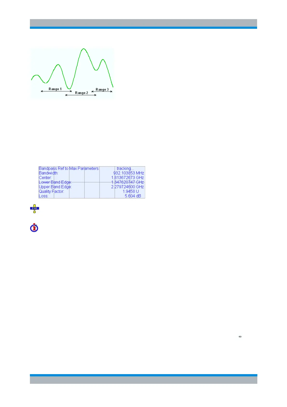
Bandfilter parameters
For a Bandpass/Bandstop Ref to Marker search, the info field contains the following search results:
Bandwidth is the n-dB bandwidth of the bandpass/bandstop region, where n is the selected x dB
Bandwidth. The bandwidth is equal to the difference between the Upper Bandwidth Edge (UBE)
and the Lower Bandwidth Edge (LBE).
Center is calculated as the geometric mean value of the LBE and UBE positions: f
Center
= sqrt (f
LBE
* f
UBE
). If desired, the center frequency can be calculated as the arithmetic mean value f
Center
=
(f
LBE
+ f
UBE
)/2; see System – System Config... – General.
Lower Band Edge is the closest frequency below the center frequency where the trace is equal to
the center value minus n dB.
Upper Band Edge is the closest frequency above the center frequency where the trace is equal to
the center value minus n dB.
The Quality Factor is the ratio between the Center frequency and the 3-dB Bandwidth; it does not
depend on the selected x dB Bandwidth.
Loss is the loss of the filter at its center frequency and is equal to the response value of marker
no. 4. For an ideal bandpass filter the loss is zero (0 dB), for an ideal bandstop filter it is – dB.
For a Bandpass/Bandstop Ref to Marker search, the following modified definitions apply:
Lower Band Edge is the closest frequency below the active marker position where the trace is