R&S
®
ZVA / R&S
®
ZVB / R&S
®
ZVT GUI Reference
Trace Menu
Operating Manual 1145.1084.12 – 30 215
M 1 indicates the minimum of the peak (Min).
M 2 indicates the point on the left edge of the peak where the trace value is equal to the maximum
in the search range (passband value) minus x dB Bandwidth (Lower Band Edge, LBE).
M 3 indicates the point on the right edge of the peak where the trace value is equal to the
maximum in the search range (passband value) minus x dB Bandwidth (Upper Band Edge, UBE).
M 4 indicates the center of the peak, calculated as the geometric mean value of the LBE and UBE
positions: f
Center
= sqrt (f
LBE
* f
UBE
).
The bandfilter search results are displayed in the bandfilter info field.
To search for a bandpass region in the vicinity of the active marker, use Bandpass Search Ref to
Marker. Use Bandfilter Tracking to select other search modes.
CALCulate<Chn>:MARKer<Mk>:FUNCtion:BWIDth:MODE BSTOP
CALCulate<Chn>:MARKer<Mk>:FUNCtion:EXECute BFILter
Bandfilter Tracking
Causes the bandfilter search to be repeated after each sweep: When tracking mode is active the markers
typically change their horizontal and their vertical positions as the measurement goes on.
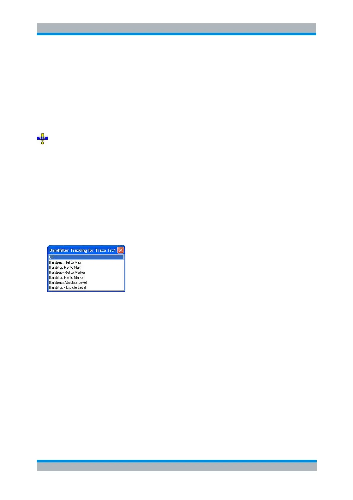
Tracking for the different bandfilter search modes is enabled or disabled in a selection box. Selecting a
search mode for tracking also activates this mode.
The search modes have the following effect:
Bandpass Ref to Max / Bandstop Ref to Max: The bandpass / bandstop is the tallest / lowest peak
in the search range.
Bandpass / Bandstop Ref to Marker: The bandpass / bandstop is the peak in the vicinity of the
active marker position. The response values for the lower and upper band edges are calculated
as the response values at the active marker position plus / minus x dB, where x is equal to the <x
dB Bandwidth>. To be valid the peak must be above / below the response value for the band
edges, and the band edges must fall into the search range.
Bandpass / Bandstop Absolute Level: The bandpass / bandstop is the tallest/lowest peak in the
search range. To be valid, the peak must be above / below –x dB, where x is numerically equal to
the <x dB Bandwidth> value. The Lower Band Edge and Upper Band Edge values are given by
the frequencies where the trace is equal to –x dB.
Tracking is a toggle function: Selecting the function repeatedly switches the tracking mode on and off.
CALCulate<Chn>:MARKer<Mk>:FUNCtion:BWIDth:MODE
CALCulate<Chn>:MARKer<Mk>:FUNCtion:EXECute BFILter
CALCulate<Chn>:MARKer<Mk>:SEARch:TRACking