R&S
®
ZVA / R&S
®
ZVB / R&S
®
ZVT GUI Reference
Trace Menu
Operating Manual 1145.1084.12 – 30 213
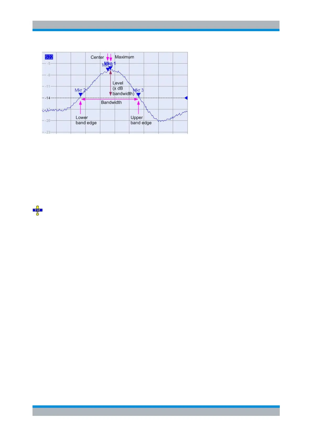
M 1 indicates the maximum of the peak (Max).
M 2 indicates the point on the left edge of the peak where the trace value is equal to the maximum
minus x dB Bandwidth (Lower Band Edge, LBE).
M 3 indicates the point on the right edge of the peak where the trace value is equal to the
maximum minus x dB Bandwidth (Upper Band Edge, UBE).
M 4 indicates the center of the peak, calculated as the geometric mean value of the LBE and UBE
positions: f
Center
= sqrt (f
LBE
* f
UBE
).
The bandfilter search results are displayed in the bandfilter info field.
To search for a bandpass region in the vicinity of the active marker, use Bandpass Search Ref to
Marker.
CALCulate<Chn>:MARKer<Mk>:FUNCtion:BWIDth:MODE BPASs
CALCulate<Chn>:MARKer<Mk>:FUNCtion:EXECute BFILter
Bandpass Search Ref to Marker
Activates the search for a bandpass region on the active trace in the vicinity of the active marker and
activates bandfilter Tracking. The bandpass region is the frequency range between the lower and the
upper band edge; the band edges are defined by the magnitude of the trace at the marker position minus
the x dB Bandwidth parameter: