R&S
®
ZVA / R&S
®
ZVB / R&S
®
ZVT GUI Reference
Trace Menu
Operating Manual 1145.1084.12 – 30 230
fail can be generated in addition.
Limit check and display of the limit lines are independent of each other: With disabled limit check, the
limit line can still be displayed.
If no limit lines are defined for the active trace, the limit check can be switched on but will always PASS
the trace.
Limits are checked at the actual measurement points, whereas a limit failure is indicated for the trace
segments on both sides of a failed point. A small number of points causes wide trace segments so that the
out-of tolerance regions can appear wider as they are.
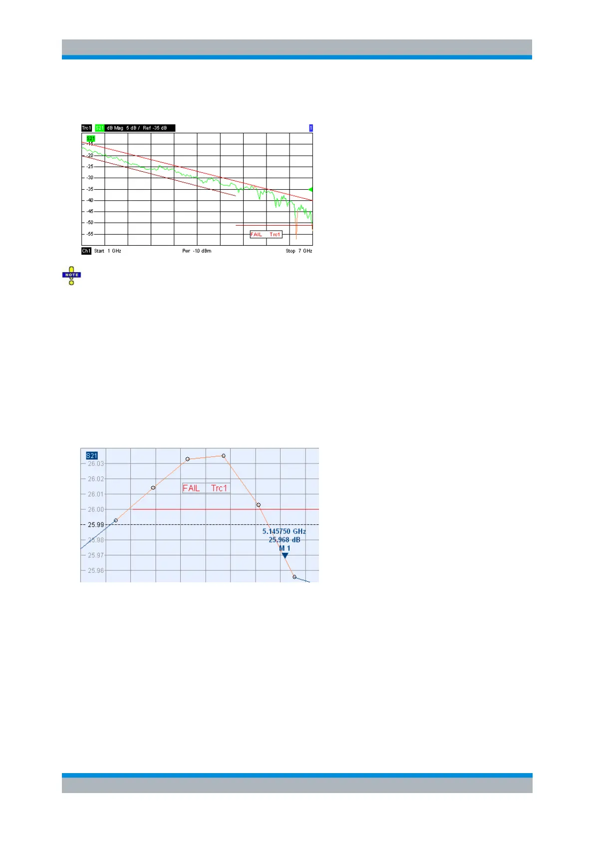
Markers show interpolated values. As a consequence, a trace segment can be failed, whereas a marker
placed on the segment may show a response value within the allowed range. This is shown in the
example below, with an upper limit line at 26 dB, and a marker response value of 25.968 dB. The small
circles correspond to the sweep points; the orange part of the trace is failed.
CALCulate<Chn>:LIMit:STATe ON | OFF
CALCulate<Chn>:LIMit:LOWer:STATe ON | OFF
CALCulate<Chn>:LIMit:UPPer:STATe ON | OFF
CALCulate<Chn>:LIMit:FAIL?
Ripple Test
The commands in the second section of the Lines submenu define the ripple test. A ripple test is a special
type of limit test where the maximum difference between the largest and the smallest response value of
the trace must not exceed the specified limit. This test is suitable e.g. to check whether the passband