R&S
®
ZVA / R&S
®
ZVB / R&S
®
ZVT GUI Reference
Channel Menu
Operating Manual 1145.1084.12 – 30 257
The power corresponds to the actual output power at the test port that supplies the stimulus for the active
channel or at the calibrated reference plane. Any generator power calibration or attenuation of the active
generator step attenuators is taken into account. The wide range of power stimulus values leaves enough
flexibility to include an attenuation or gain in the test setup.
[SENSe<Ch>:]SWEep:TYPE POWer
SEGMent[SENSe<Chn>:]FUNCtion[:ON] "XPOWer:..."
SOURce<Ch>:FREQuency<Pt>:CW|FIXed
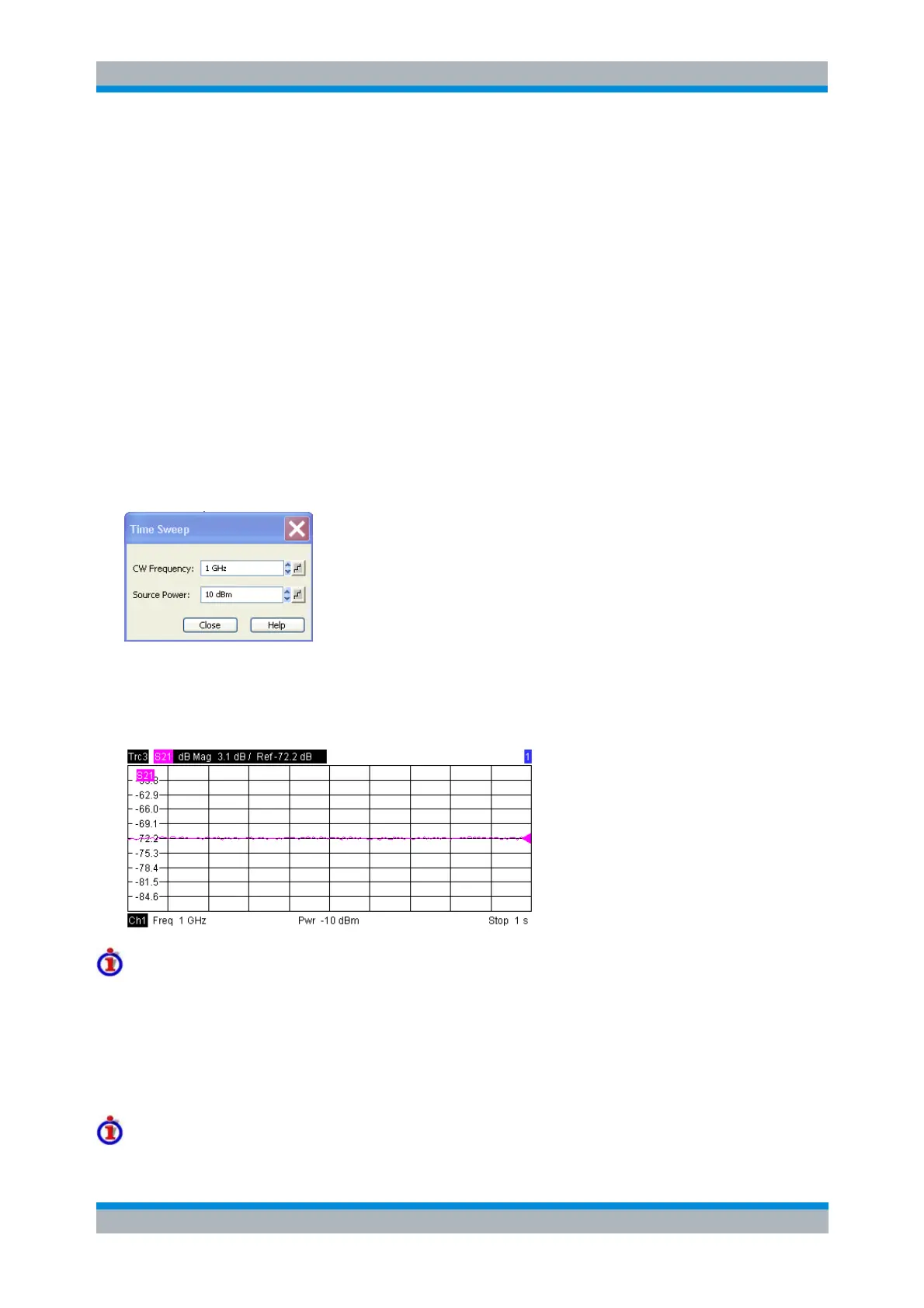
Time
Time sweeps are performed at constant frequency and stimulus power. A single sweep extends over a
specified period of time. The sweep time is defined via Channel - Stimulus - Stop; see Stimulus and
Sweep Types. The time intervals between two consecutive sweep points are calculated according to
<Stop>/(n - 1) where n is the selected Number of Points. The frequency (CW Frequency) and internal
generator power (Source Power) is fixed and entered into a field which pops up as soon as Time is
activated:
A Time sweep corresponds to the analysis of a signal over the time; the function of the analyzer is
analogous to an oscilloscope. In a Cartesian diagram the measurement result is displayed as a trace over
a linear time scale (oscillographic representation). The following example shows a Time sweep with a
DUT that does not change its characteristics in time:
Sweep time
The minimum sweep time depends on the number of measurement points, the measurement bandwidth,
the delay time before each partial measurement and the number of partial measurements required for
each measurement point. The analyzer estimates this time, taking into account the current measurement
settings.
If the total sweep time entered via Channel - Stimulus - Stop is smaller than the estimated minimum
sweep time, the analyzer opens a dialog to adjust (increase) the stop time.
Equidistance of sweep points