R&S
®
ZVA / R&S
®
ZVB / R&S
®
ZVT GUI Reference
Channel Menu
Operating Manual 1145.1084.12 – 30 274
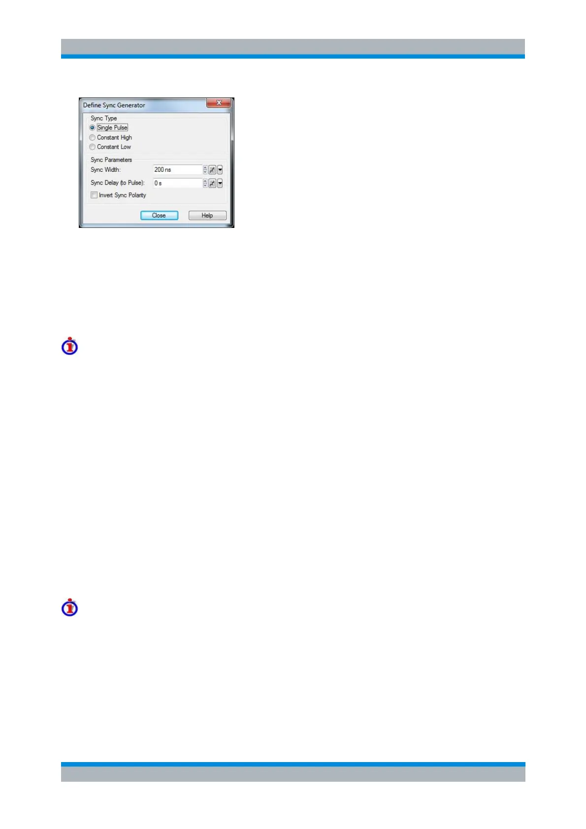
The sync signal is either a single pulse signal with definite pulse width (Sync Width), following the pulse
generator signal by a specified Sync Delay (to Pulse), or a constant signal. Constant signals (Constant
High and Constant Low) need no further specification. It is possible to invert the polarity of the sync signal,
i.e. to exchange the high signal and low signal periods.
While the pulse generator signal type is Constant High or Constant Low, the sync generator signal type is
Constant High or Constant Low, too.
See also background information on Pulse Generator Signals.
Timing Restrictions
If the Sync Width is greater than or equal to the Pulse (Train) Period, a constant sync signal is
generated.
Otherwise, in case the Sync Delay is set to a negative value or to a value greater than the Pulse
(Train) Period T, it is internally shifted by multiples of T so that the resulting value is in the interval
[0,T).
If (after this operation) the sync pulse overlaps with the pulse (train), the time origin is shifted to
the rising edge of the first sync pulse.
[SENSe<Ch>:]PULSe:GENerator2:TYPE
[SENSe<Ch>:]PULSe:GENerator2:WIDTh
[SENSe<Ch>:]PULSe:GENerator1:DELay
[SENSe<Ch>:]PULSe:GENerator2:POLarity
Adjust Settings for Chopped Pulse Profile
Defines the time resolution for the chopped pulse profile mode and activates the mode. This dialog is
called from the Define Pulse Generator dialog.
Chopped pulse profile mode
Chopped pulsed profile mode is a means of achieving extremely small time resolutions for measurements
on strictly periodic signals. Time resolution is the critical parameter for measurements on pulsed signals
with very short pulse widths. In a normal time sweep at the default IF bandwidth of 10 kHz, the time
resolution (i.e. the measurement time for each sweep point) is in the 100 μs range. In chopped pulse
profile mode, the analyzer achieves time resolutions down to 12.5 ns.
A power calibration is generally not possible, however, the measurement provides accurate relative power
levels at consecutive sweep points. Hence the measurement result shows the profile of the measured RF
signal.