RL78/G1H CHAPTER 15 SERIAL INTERFACE IICA
R01UH0575EJ0120 Rev. 1.20 Page 508 of 920
Dec 22, 2016
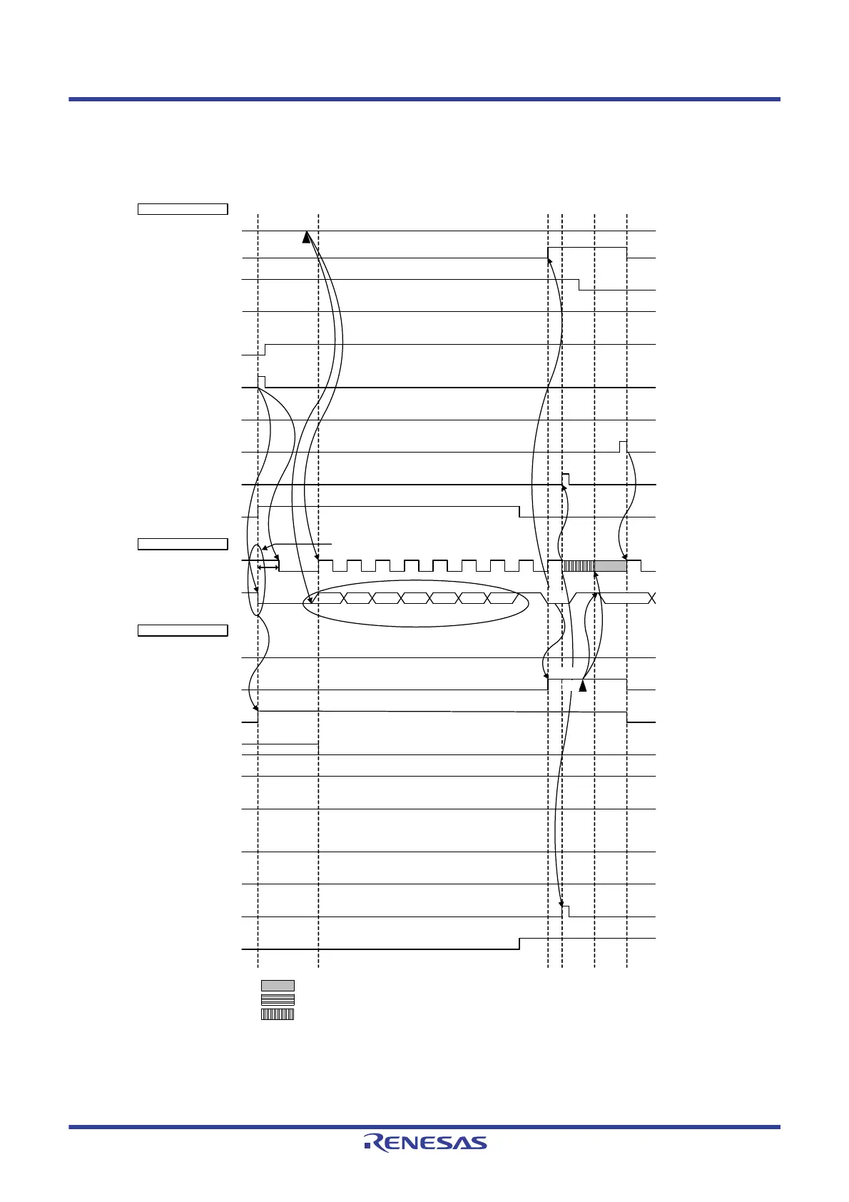
Figure 15 - 44 Example of Slave to Master Communication
(When 8-Clock Wait Is Selected for Master, 9-Clock Wait Is Selected for Slave) (1/3)
(1) Start condition ~ address ~ data
Note 1. For releasing wait state during reception of a master device, write “FFH” to IICAn or set the WRELn bit.
Note 2. Make sure that the time between the fall of the SDAAn pin signal and the fall of the SCLAn pin signal is at least 4.0
μs when specifying standard mode and at least 0.6 μs when specifying fast mode.
Note 3. Write data to IICAn, not setting the WRELn bit, in order to cancel a wait state during transmission by a slave device.
Remark n = 0, 1
ACKDn
(ACK detection)
IICAn
WTIMn
(8 or 9 clock wait)
ACKEn
(ACK control)
MSTSn
(communication status)
STTn
(ST trigger)
SPTn
(SP trigger)
WRELn
(wait cancellation)
INTIICAn
(interrupt)
Bus line
TRCn
(transmit/receive)
Master side
SCLAn (bus)
(clock line)
SDAAn (bus)
(data line)
Slave side
IICAn
ACKDn
(ACK detection)
STDn
(ST detection)
SPDn
(SP detection)
WTIMn
(8 or 9 clock wait)
ACKEn
(ACK control)
MSTSn
(communication status)
WRELn
(wait cancellation)
INTIICAn
(interrupt)
TRCn
(transmit/receive)
Slave address
Start condition
<1>
<4>
<3>
AD6 R
D17
ACK
Note 2
: Wait state by master device
: Wait state by slave device
: Wait state by master and slave devices
AD5 AD4 AD3 AD2 AD1 AD0
<2>
<5>
<7> Note 1
Note 3
<6>
H
L
H
H
L
L
 Loading...


