RL78/G1H CHAPTER 18 RF TRANSCEIVER
R01UH0575EJ0120 Rev. 1.20 Page 565 of 920
Dec 22, 2016
(5) RSSI/CCA result register (BBRSSICCARSLT)
Stores the result data of CCA/ED or RSSI.
The CCA result select bit can be used to switch between the CCA/ED value and the RSSI value.
The result corresponding to the save bank which is specified by the receive data save bank select bit is read
out when reading the RSSI value.
The read data is expressed as 2’s complement. The unit is dBm (ex. ”19EH” is ”-98dBm”).
The BBRSSICCARSLT register is read by the serial interface in 8-bit units.
Reset signal generation clears this register to 0000H.
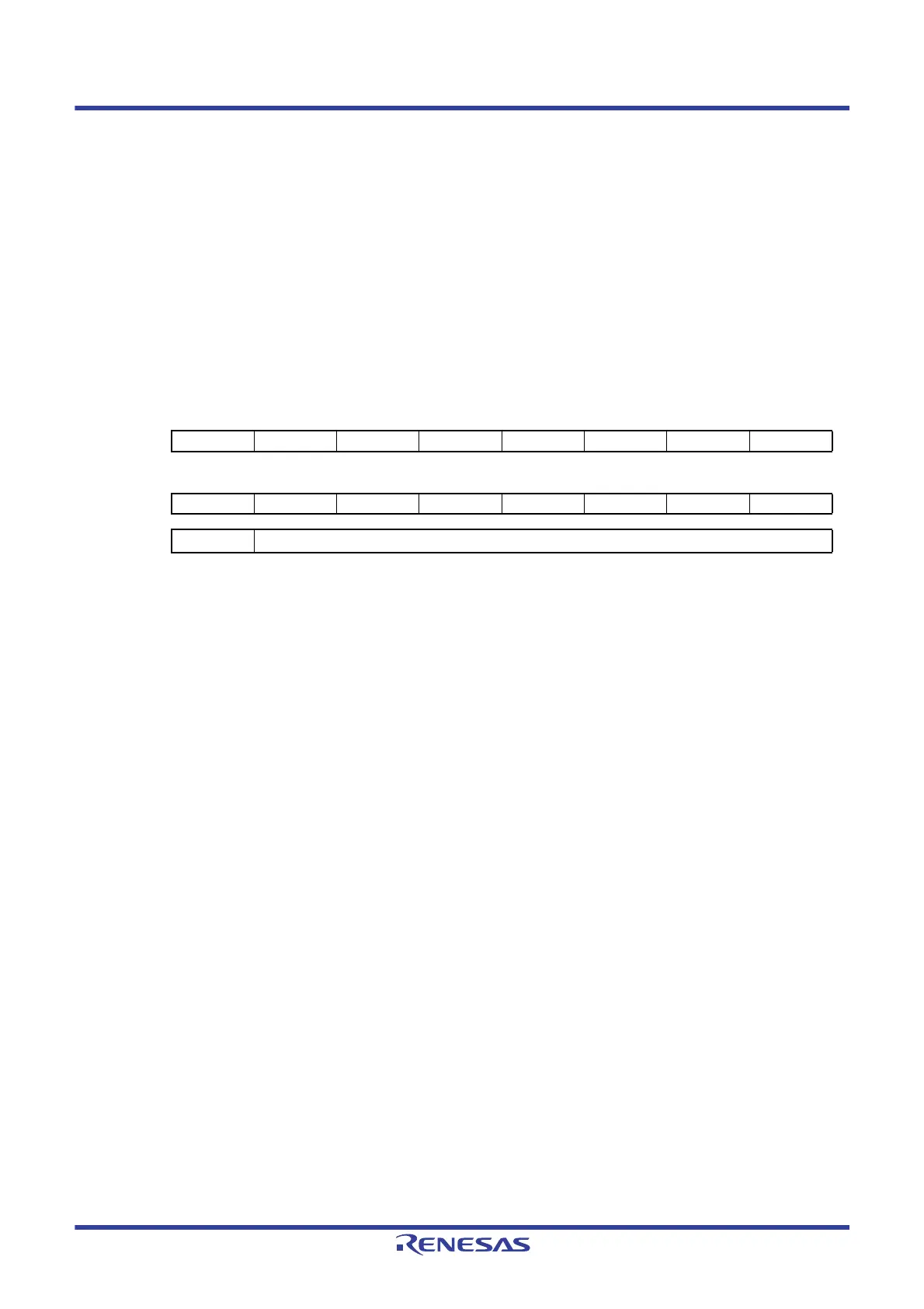
Figure 18 - 11 RSSI/CCA Result Register (BBRSSICCARSLT) Format
Caution “0” is always read for bits 15 to 9.
The loss of antenna input signal revel defers causing LSI board layout and usage of RFSW or SAW filter.
Therefore, setting values are required modification to match the input level and value of RSSI/CCA result
register (BBRSSICCARSLT). The value of receive level threshold setting register (BBLVLVTH) also required
modification.
Set values in Table 18 - 7 Register setting for loss of input signal level from antenna in IDLE state to cancel
the loss. The values are deferent for operation enabled/disabled FEC.
The values in Table 18 - 52 to Table 18 - 59 Settings Required for Each Data Rate are reference measured
on evaluation board of Renesas Electronics.
Caution Refer to the latest application note for setting data in Table 18 - 7 when to use the product.
Address:
0005H, 0004H
After reset:
0000H
R
Symbol 15 14 13 12 11 10 9 8
BBRSSIC
CARSLT
0000000CCARSLT8
76543210
CCARSLT7 CCARSLT6 CCARSLT5 CCARSLT4 CCARSLT3 CCARSLT2 CCARSLT1 CCARSLT0
CCARSLT[8:0]
RSSI/CCA result data
 Loading...


