RL78/G1H CHAPTER 23 VOLTAGE DETECTOR
R01UH0575EJ0120 Rev. 1.20 Page 767 of 920
Dec 22, 2016
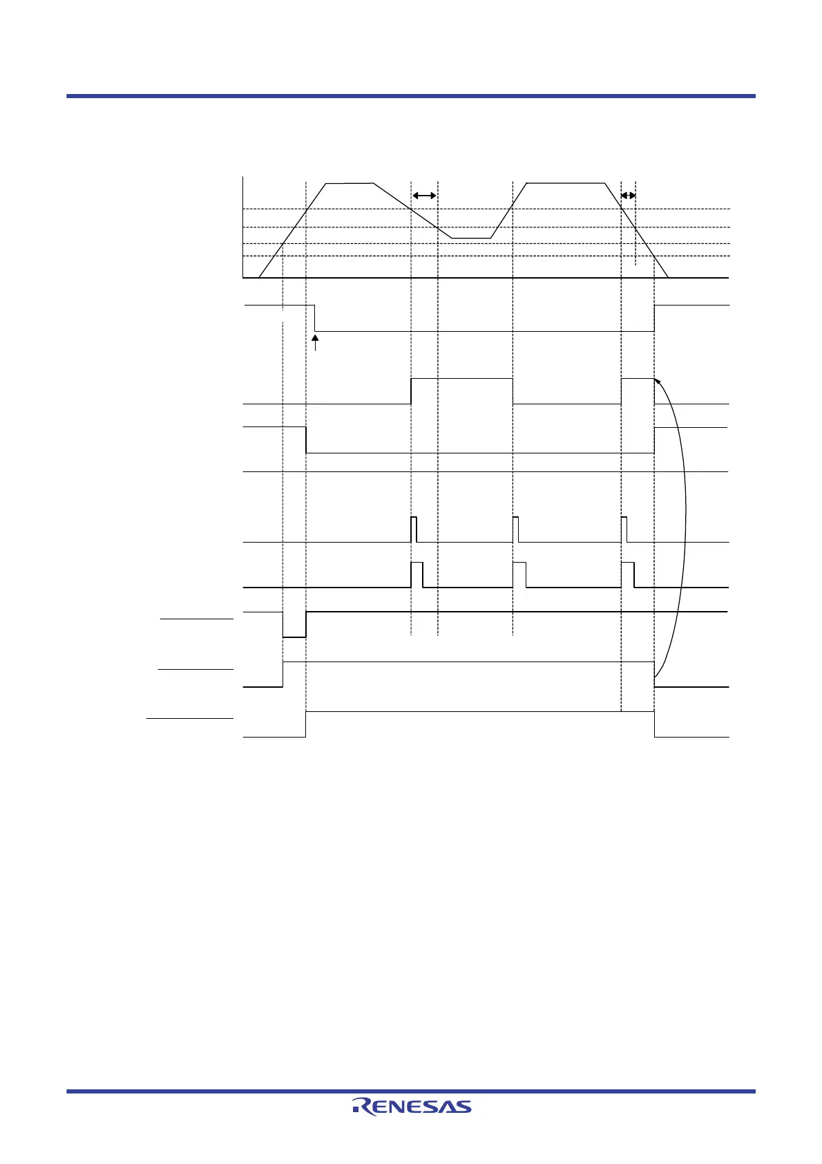
Figure 23 - 5 Timing of Voltage Detector Internal Interrupt Signal Generation
(Option Byte LVIMDS1, LVIMDS0 = 0, 1)
Note 1. The LVIMK flag is set to “1” by reset signal generation.
Note 2. When the voltage falls, this LSI should be placed in the STOP mode, or placed in the reset state by controlling the
externally input reset signal, before the voltage falls below the operating voltage range defined in 31.4 AC
Characteristics. When restarting the operation, make sure that the operation voltage has returned within the range of
operation.
Remark V
POR: POR power supply rise detection voltage
V
PDR: POR power supply fall detection voltage
H
Time
INTLVI
LVIF flag
LVIMD flag
LVIMK flag
(interrupt MASK)
(set by software)
LVILV flag
Internal reset signal
POR reset signal
LVD reset signal
Supply voltage (VDD)
V
LVD
VPOR = 1.51 V (TYP.)
V
PDR = 1.50 V (TYP.)
LVIIF flag
Note 2
Note 2
Cleared
Cleared by
software
H
Note 1
Lower limit of operation voltage
 Loading...


