RL78/G1H CHAPTER 23 VOLTAGE DETECTOR
R01UH0575EJ0120 Rev. 1.20 Page 769 of 920
Dec 22, 2016
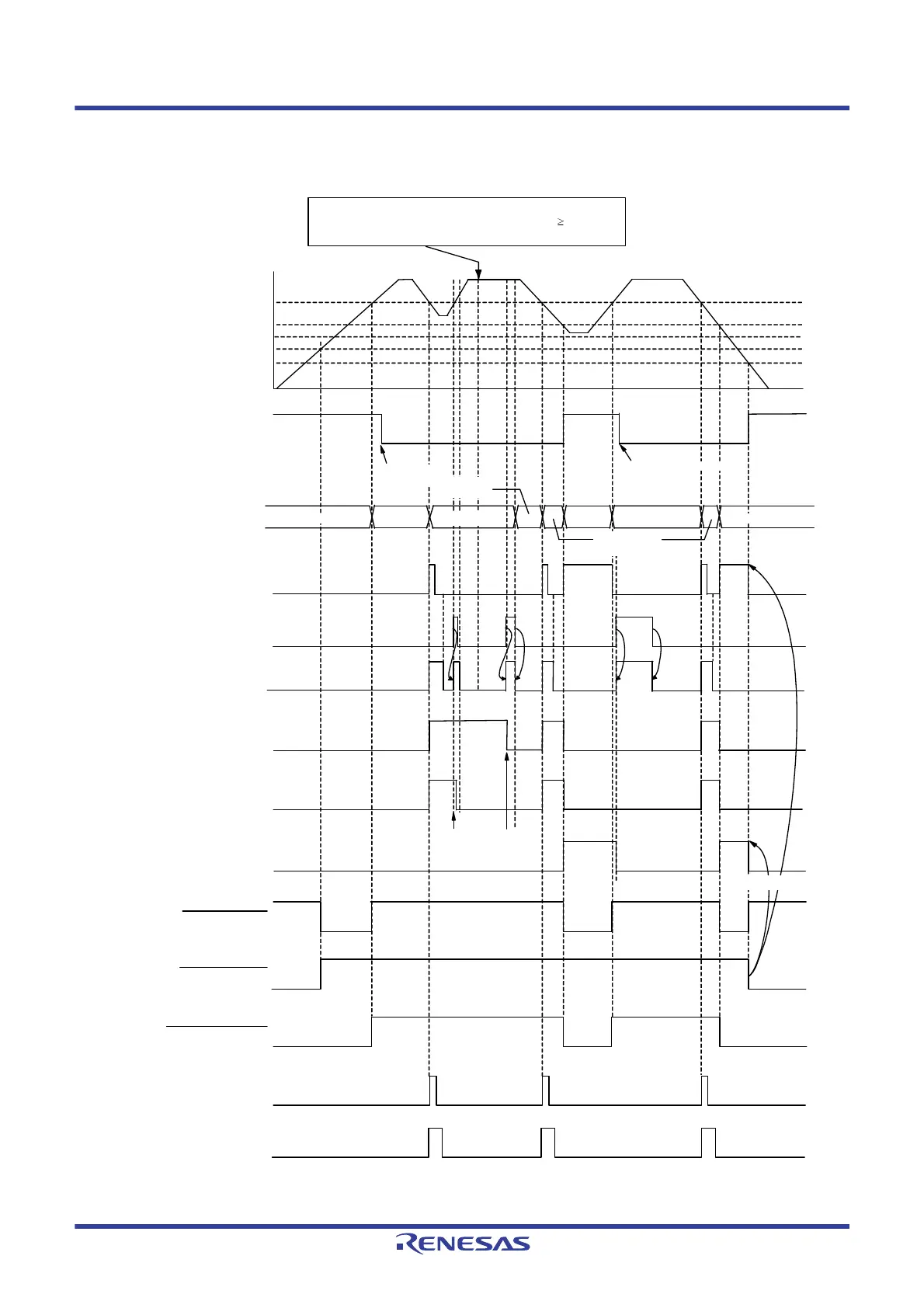
Figure 23 - 6 Timing of Voltage Detector Reset Signal and Interrupt Signal Generation
(Notes and Remark are listed on the next page.)
(Option Byte LVIMDS1, LVIMDS0 = 1, 0) (1/2)
注2
If a reset is not generated after releasing the mask ,
determine that a condition of V
DD
becomes V
DD
V
LVDH
,
clear LVIMD bit to 0, and the MCU shift to normal operation.
LVIF flag
LVIOMSK flag
Operation status
LVIIF flag
INTLVI
LVIMD flag
LVIRF flag
LVILV flag
Internal reset signal
POR reset signal
LVD reset signal
Supply voltage (VDD)
V
LVDL
VPOR = 1.51 V (TYP.)
V
PDR = 1.50 V (TYP.)
V
LVDH
LVIMK flag
(set by software)
LVISEN flag
(set by software)
Lower limit of operation voltage
Time
H
Note 1
Cleared by
software
RESET
Normal
operation
RESET
Normal
operation
RESET
Save
processing
Cleared
Cleared by software
Save
processing
Normal
operation
Cleared by
software
Note 2
Cleared
 Loading...


