RL78/G1H CHAPTER 31 ELECTRICAL SPECIFICATIONS
R01UH0575EJ0120 Rev. 1.20 Page 869 of 920
Dec 22, 2016
Note 1. Current flowing to VDD.
Note 2. When high speed on-chip oscillator and high-speed system clock are stopped.
Note 3. Current flowing only to the real-time clock (RTC) (excluding the operating current of the low-speed on-chip oscillator and
the XT1 oscillator). The supply current of the RL78 microcontrollers is the sum of the values of either I
DD1 or IDD2, and
I
RTC, when the real-time clock operates in operation mode or HALT mode. When the low-speed on-chip oscillator is
selected, I
FIL should be added. IDD2 subsystem clock operation includes the operational current of the real-time clock.
Note 4. Current flowing only to the 12-bit interval timer (excluding the operating current of the low-speed on-chip oscillator and
the XT1 oscillator). The supply current of the RL78 microcontrollers is the sum of the values of either I
DD1 or IDD2, and IIT,
when the 12-bit interval timer operates in operation mode or HALT mode. When the low-speed on-chip oscillator is
selected, I
FIL should be added.
Note 5. Current flowing only to the watchdog timer (including the operating current of the low-speed on-chip oscillator).
The supply current of the RL78 microcontrollers is the sum of I
DD1, IDD2, or IDD3 and IWDT when the watchdog timer is in
operation.
Note 6. Current flowing only to the A/D converter. The supply current of the RL78 microcontrollers is the sum of I
DD1 or IDD2 and
I
ADC when the A/D converter operates in an operation mode or the HALT mode.
Note 7. Current flowing only to the LVD circuit. The supply current of the RL78 microcontrollers is the sum of I
DD1, IDD2, or IDD3
and ILVD when the LVD circuit is in operation.
Note 8. Current flowing during programming of the data flash.
Note 9. Current flowing during self-programming.
Note 10. For shift time to the SNOOZE mode, see 20.3.3 SNOOZE mode.
Remark 1. f
IL: Low-speed on-chip oscillator clock frequency
Remark 2. f
SUB: Subsystem clock frequency (XT1 clock oscillation frequency)
Remark 3. f
CLK: CPU/peripheral hardware clock frequency
Remark 4. Temperature condition of the TYP. value is T
A = 25 °C
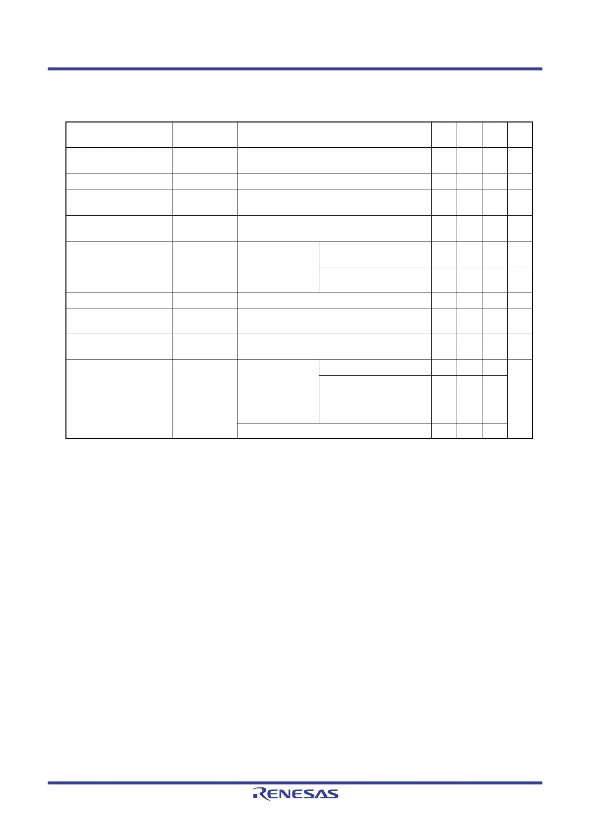
Peripheral Functions (Common to all products)
(T
A = ‒40 to +85 °C, 1.8 V ≤ VDD ≤ 3.6 V, VSS = 0 V)
Parameter Symbol Conditions MIN. TYP. MAX
.
Unit
Low-speed on-chip oscillator
operating current
I
FIL
Note 1
0.20 μA
RTC operating current
I
RTC
Notes 1, 2, 3
0.02 μA
12-bit interval timer
operating current
I
IT
Notes 1, 2, 4
0.02 μA
Watchdog timer operating
current
I
WDT
Notes 1, 2, 5
fIL = 15 kHz 0.22 μA
A/D converter operating
current
I
ADC
Notes 1, 6
When conversion at
maximum speed
Normal mode,
AV
REFP = VDD = 3.3 V
1.3 1.7 mA
Low voltage mode,
AV
REFP = VDD = 3.0 V
0.5 0.7 mA
LVD operating current
I
LVD
Notes 1, 7
0.08 μA
Self-programming operating
current
I
FSP
Notes 1, 9
2.50 12.2
0
mA
BGO operating current
I
BGO
Notes 1, 8
2.50 12.2
0
mA
SNOOZE operating current
I
SNOZ
Note 1
ADC operation
The mode is performed
Note 10
0.50 0.60 mA
The A/D conversion
operations are performed,
Low voltage mode,
AV
REFP = VDD = 3.0 V
1.20 1.44
DTC operation 3.10
 Loading...


