360
Simple P/P Software
Chapter 10 Special Functions
a) In DSK mode, the backgrounds that can be selected in the PGM Config menu are restricted to
background 1 and background 2.
b) Depends on the setting in the Engineering Setup >Switcher >Config >M/E Output Assign menu.
OUT5 and OUT6 cannot be used.
Connectors for which a P/P row output signal can be selected
For an edit preview bus or AUX bus assigned to output connector OUT23 or
OUT24, you can select a P/P row output signal.
If these buses are assigned to other than OUT23 or OUT24, then it is not
possible to select a P/P row output signal. (Assigning these buses to the two
connectors is recommended.)
Logical assignment of the physical PGM/PST
In the Engineering Setup >Switcher >Config >Logical M/E Assign menu, it is
not possible to assign the physical PGM/PST as a logical PGM/PST.
In the <Logical M/E to Physical P/P> group, you can select from M/E-1, M/E-
2, and M/E-3.
Configuration of the switcher bank outputs
If Multi Program mode is selected in setup (M/E Config in the Switcher
>Config menu), then for Bkgd in the PGM Config menu, it is only possible to
select Clean.
OUT19 Preview
P/P OUT2
b)
Key preview 1
OUT20 Clean
P/P OUT3
b)
Key preview 2
OUT21 Key preview
P/P OUT4
b)
Clean 1
OUT22 Preset Preset Clean 2
Output connector Assignable bus
OUT23 Edit preview bus
OUT24 AUX bus
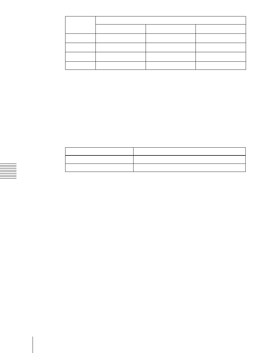
Output
connector
Fixed assigned outputs
Standard mode Multi-program mode
DSK mode
a)