5 Operation
Lifting
1
2
6210_003-027
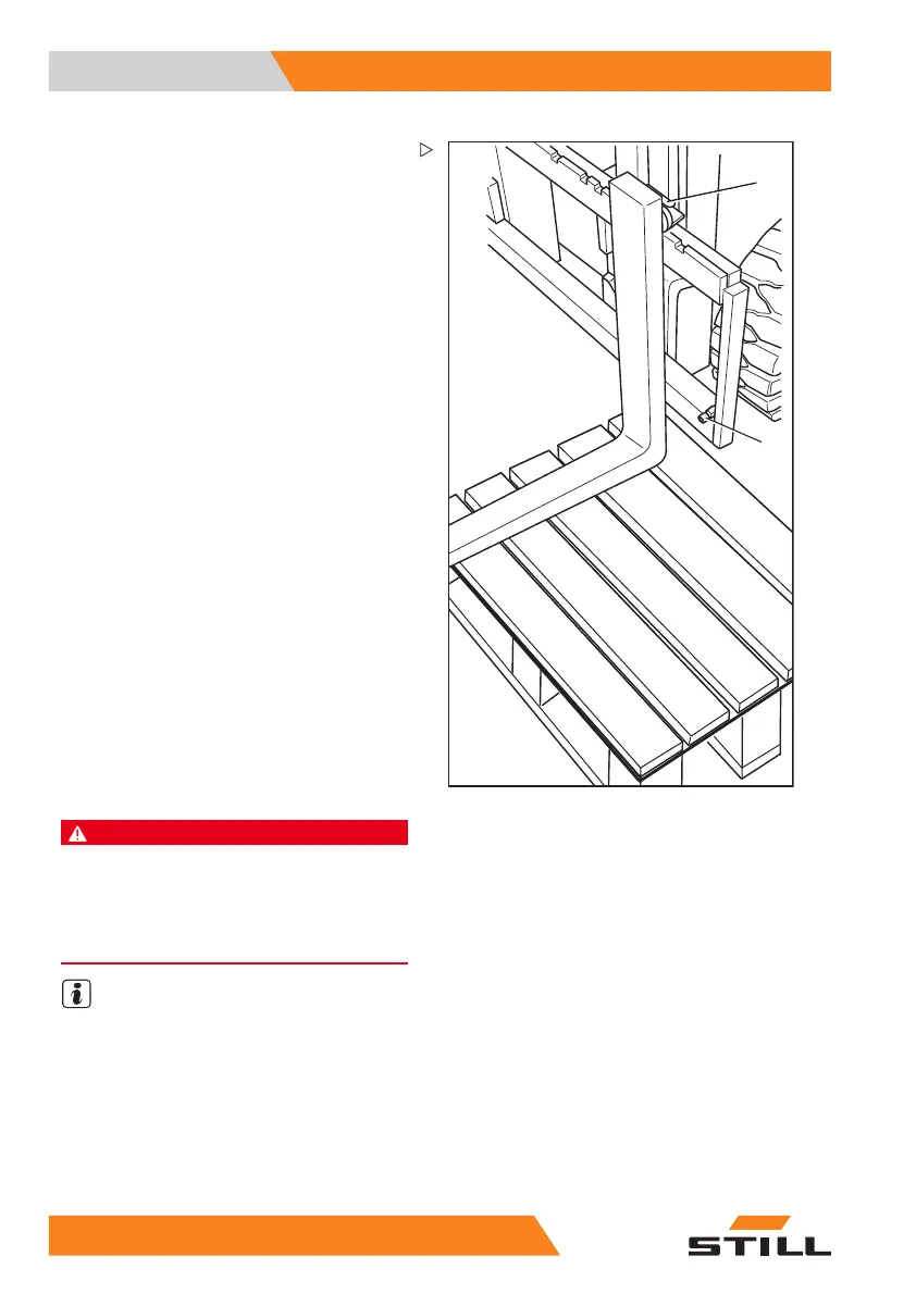
Removal
– Select a pallet corresponding to the fork arm
size.
– Position the pallet to the left
or right of the
fork carriage.
– Raise the fork carriage until the lower edges
of the fork arms are approx.3 cm higher than
the height of the pallet.
– Actuate the parking brake and make sure it
is applied securely.
– Turn the switch key to the le
ft and remove it.
– Undo the locking screw (2) on the right or
left.
– Pull the locking lever (1) upwards and push
the fork arms outwards onto the pallet.
Installation
– Position the fork arms to
the left or right of
theforkcarriageonap
allet.
– Push the fork arms onto the fork carriage
from the outside towards the centre.
– Pull the locking lever (1) upwards and push
the fork arms into the required position.
Ensure that the locking lever snaps into
place.
– Fit and tighten the lo
cking screw (2).
DANGER
There is a risk to life caused by a falling load or fork!
– Tighten the locking screw after every fork
replacement.
– It is not permitted to drive or transport loads
without the locking screw.
NOTE
If the truck is equipped with the "load measu-
rement" comfort feature, then a "zero adjust-
ment of the load measurement" is imperative
after the fork arms have been changed; see
⇒ Chapter "Zero adjustment of the load mea-
surement (variant)", P. 5-101. Otherwise
correct measurement of the load cannot be
guaranteed.
14
2 55048011501 EN - 12/2015