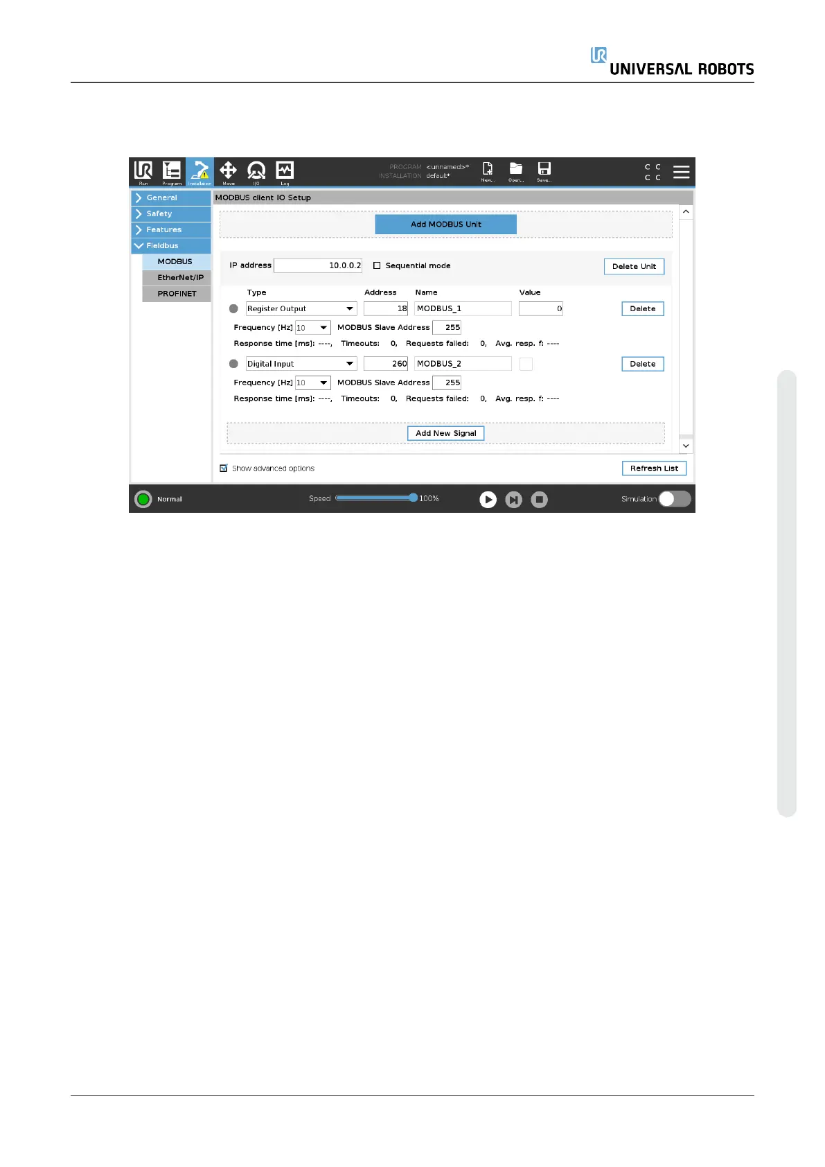
24.19. MODBUS Client I/O Setup
Here, the MODBUS client (master) signals can be set up. Connections to MODBUS servers (or
slaves) on specified IP addresses can be created with input/output signals (registers or digital).
Each signal has a unique name so it can be used in programs.
24.19.1. Refresh
Push this button to refresh all MODBUS connections. Refreshing disconnects all modbus units, and
connects them back again. All statistics are cleared.
24.19.2. Add unit
Push this button to add a new MODBUS unit.
24.19.3. Delete unit
Push this button to delete the MODBUS unit and all signals on that unit.
24.19.4. Set unit IP
Here the IP address of the MODBUS unit is shown. Press the button to change it.
User Manual 233 UR5e
24.Installation Tab
Copyright © 2009–2021 by UniversalRobotsA/S. All rights reserved.

 Loading...


